
Soil Resistivity Measurement
Soil Resistivity is necessary when designing the earthing (grounding) system for new installations to meet your earth (ground) resistance requirements. The ideal location would be the where the lowest possible resistance would be. Poor soil conditions can be overcome with more elaborate earthing (grounding) systems. For an earthing (grounding) system to be effective, it should be designed to withstand the worst possible conditions.
Soil composition, moisture content, and temperature all impact the soil resistivity. Soil is rarely homogenous and the resistivity of the soil will vary geographically and at different soil depths.
Moisture content changes seasonally, varies according to the nature of the sub layers of earth, and the depth of the permanent water table. Since soil and water are generally more stable at deeper strata, it is recommended that the earth (ground) rods be placed as deep as possible into the earth, at the water table if possible. Earth (ground) rods should be installed where there is a stable temperature.
Soil Resistivity
The universally accepted soil resistivity measurement procedure is the Wenner method developed by Dr. Frank Wenner of the US Bureau of Standards in 1915. (F. Wenner, A Method of Measuring Earth Resistivity; Bull, National Bureau of Standards, Bull 12(4) 258, p. 478-496; 1915/16.)
Example: A three (3) meter long earth (ground) rods is part of your grounding system. To measure the soil resistivity at a depth of three (3) meters, the spacing between the test electrodes should at least be three (3) meters.
Example:
A = 3 meters, distance between probes and
R = 100 ohms, measured resistance
Then the soil resistivity would equal:


Soil Resistance
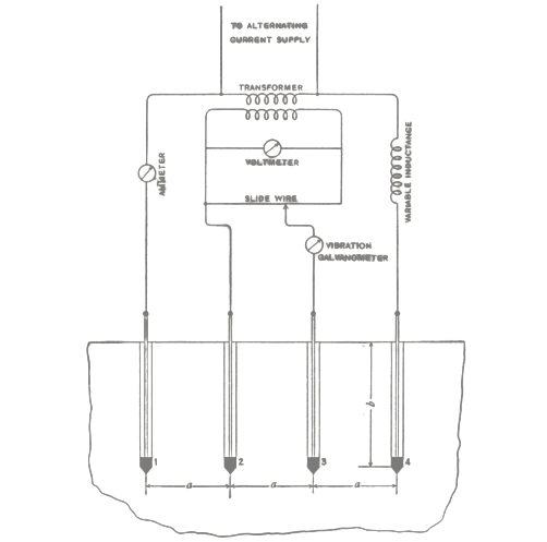
As you can see, four earth earth (ground) stakes are positioned in the soil in a straight line, equidistant from one another. The distance between earth earth (ground) stakes should be at least three times greater than the stake depth. The test equipment generates a known current through the two outer earth (ground) stakes and the drop in voltage potential is measured between the two inner earth (ground) stakes. Using Ohm's Law (V=IR), the soil resistance can be calculated.
Because measurement results are often distorted and invalidated by underground pieces of metal, underground aquifers, etc. additional measurements where the stake's axis are turned 90 degrees is always recommended. By changing the depth and distance several times, a profile is produced that can determine a suitable earth (ground) resistance system.
Source: https://www.fluke.com/en-us/learn/blog/grounding/soil-resistivity