This is a continuation of the article Effect of Cable length on Variable Frequency Drive.
Cable Resonance
When dealing with Variable Frequency Drives (VFDs), the cable length between the VFD and the motor can introduce certain electrical challenges, one of which is cable resonance. Resonance occurs when the frequency of the drive's output waveform interacts with the natural frequency of the cable, creating amplified voltage reflections. This can result in damaging voltage spikes, increased electromagnetic interference (EMI), and potentially motor insulation failure.
Considerations for Cable Length and VFD Operation
Longer cable lengths can increase the likelihood of encountering resonance frequencies that coincide with the switching frequencies of the VFD.
VFDs operate at a particular switching frequency (typically between 2 kHz to 16 kHz). If the resonance frequency is close to the switching frequency, the risk of resonance increases.
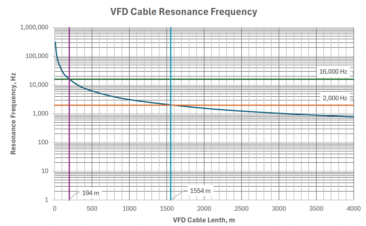
The above graph indicate relationship between the resonance frequency with respect to the cable and the switching frequency of the VFD. At a 16kHz switching frequency, the maximum VFD cable length without a filter is 194 m. However, with lower switching frequency at 2kHz, the VFD cable length can go as long as 1.5km without the requirement of an output filter.
Use of Output Filters
The use output reactors or filters to dampen resonance effects. Alternatively, lower the switching frequency of the VFD or use cables designed for VFD applications with proper impedance and insulation.
Filters are commonly used to mitigate the adverse effects of resonance and voltage reflections caused by long cable lengths in Variable Frequency Drive (VFD) systems. Here's how they help:
1. Smoothing Voltage Waveforms
VFDs generate Pulse Width Modulated (PWM) waveforms to control the motor. These PWM signals are sharp, high-frequency voltage pulses, which can cause reflections when transmitted over long cables. Filters (such as output filters) smooth out these sharp voltage edges, reducing the high-frequency content in the signal.
By filtering the high-frequency components of the PWM signal, these filters lower the risk of resonance by reducing the energy that could interact with the natural frequency of the cable. This also minimizes voltage spikes and oscillations caused by reflections.
2. Damping Voltage Reflections
Long cables between the VFD and motor create a mismatch in impedance, leading to voltage reflections. These reflections can amplify and build up due to resonance, especially when the switching frequency of the VFD matches the natural frequency of the cable.
Filters, such as line reactors or output chokes, act as impedance-matching devices that reduce the amplitude of reflected waves. This damping effect weakens the resonance and ensures that the voltage spikes are much lower in magnitude, preventing motor insulation damage and extending motor life.
3. Reducing Electromagnetic Interference (EMI)
The sharp switching transients produced by VFDs, when transmitted over long cables, can radiate electromagnetic interference (EMI). This can interfere with nearby sensitive equipment or create issues with signal integrity.
Filters like EMI filters or dv/dt filters suppress these fast voltage transients, reducing the radiated EMI. This is particularly important in environments where sensitive control systems or communication equipment are present.
4. Protecting Motor Insulation
The voltage spikes caused by resonance and reflections can exceed the motor’s insulation rating, leading to premature failure. Filters, especially dv/dt filters or sine wave filters, reduce the steepness of the voltage changes, lowering the stress on motor insulation. By reducing the dv/dt (rate of voltage change), they help protect the motor from high-voltage peaks.
Types of Filters
- dv/dt Filters: These reduce the rate of voltage change (dv/dt) of PWM signals, thereby reducing voltage spikes and reflections.
- Sine Wave Filters: These convert the PWM signal into a near-sinusoidal waveform, which eliminates most high-frequency components and resonance issues.
- Line Reactors (Inductors): These increase the inductance in the circuit, slowing down the voltage changes and providing impedance matching to dampen reflections.
- EMI Filters: Specifically designed to suppress electromagnetic noise caused by the fast switching transients.
Benefits of Using Filters
- Reduce high-frequency voltage spikes and reflections.
- Extend motor lifespan by protecting its insulation.
- Lower EMI, improving compliance with electromagnetic compatibility (EMC) standards.