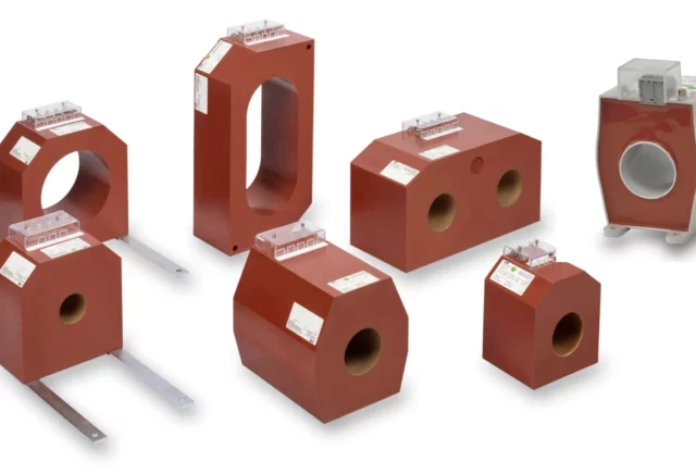
Current transformer (CT) accuracy class refers to how precisely a current transformer can replicate the primary current in its secondary winding, within certain tolerances, under defined conditions. CT accuracy is crucial because any deviation in the secondary current can impact the performance of metering devices and protection systems, leading to incorrect readings or faulty operation of protective relays.
Factors Affecting CT Accuracy Class
The accuracy class of a CT is defined by standards like IEC 61869-2, which outline how close the CT's secondary current is to the primary current over a range of currents and burdens (connected loads on the secondary side). The accuracy class is dependent on the following factors:
1. Ratio Error
This is the difference between the actual secondary current and the expected secondary current (which is a scaled version of the primary current). The ratio error is usually expressed as a percentage.
Formula:

Where
IS is the secondary current,
IP is the primary current, and
NP and NS are the number of turns in the primary and secondary windings, respectively.
2. Phase Displacement
Phase displacement is the angular difference (in degrees or minutes) between the primary current and the secondary current. In many applications, especially in protective relaying, it is important for the phase angle to be accurate to avoid relay maloperation.
3. Burden
The burden refers to the total impedance (resistance and inductance) connected to the CT’s secondary winding, typically expressed in ohms or volt-amperes (VA). The accuracy of a CT can vary depending on the burden connected, so accuracy classes are often specified at particular burden levels (e.g., 5 VA, 10 VA).
4. Accuracy Limits
CTs are classified based on their accuracy within a specific current range and burden. These ranges are important for both metering CTs and protection CTs, which serve different purposes.
5. Rated Primary Current (Ip) and Rated Secondary Current (Is)
CTs are specified with a rated primary and secondary current, commonly 5A or 1A on the secondary side. The accuracy class applies at the rated current and within a specific range of the primary current.
CT Accuracy Classes for Different Applications
CT accuracy classes differ depending on the application: metering or protection. The standards define accuracy classes using a label that denotes the permissible error.
Metering CT Accuracy Classes (IEC 61869-2)
Metering CTs are used for precise measurement of current in billing applications and must maintain high accuracy at low loads as well as at full load. Some common metering accuracy classes (IEC) are Class 0.1, 0.2, 0.5, 1, and 3. The number refers to the maximum permissible percentage ratio error at the rated primary current and at a specified burden.
For example, a CT with Class 0.2 accuracy has a ratio error of ±0.2% at rated current and burden. The lower the class number, the higher the accuracy.
- Class 0.2: Maximum ±0.2% ratio error at rated burden and rated current.
- Class 0.5: Maximum ±0.5% ratio error at rated burden and rated current.
Protection CT Accuracy Classes (IEC 61869-2)
Protection CTs are designed to accurately measure current during fault conditions, where the primary current is often much higher than normal. Protection CTs must remain accurate up to several multiples of the rated primary current.
Common Protection Classes (IEC):
- 5P
The CT has a 5% maximum composite error at a specific multiple (accuracy limit factor) of its rated primary current. - 10P
The CT has a 10% maximum composite error at a specific multiple of the rated primary current.
The number "P" stands for protection, and the number before the "P" refers to the maximum allowable error under fault conditions. For example, a Class 5P20 CT has a maximum composite error of 5% when the primary current reaches 20 times the rated primary current.
Accuracy Limit Factor (ALF)
The Accuracy Limit Factor (ALF) follows the accuracy class, representing the multiple of the rated primary current up to which the CT will maintain the specified accuracy. For instance, Class 5P20 means the CT will remain accurate with a maximum error of 5% up to 20 times the rated primary current.
Example of Accuracy Classes in Practice
Metering CT: Class 0.5, burden of 10 VA.
If the primary current is 100 A and the secondary is 5 A, a Class 0.5 CT can have a maximum error of ±0.5% at rated current, meaning the secondary current could vary between 4.975 A and 5.025 A.
Protection CT: Class 5P10.
If the primary current is 100 A, the CT must provide an accurate secondary current with no more than 5% error up to 10 times the primary current (i.e., up to 1000 A).
