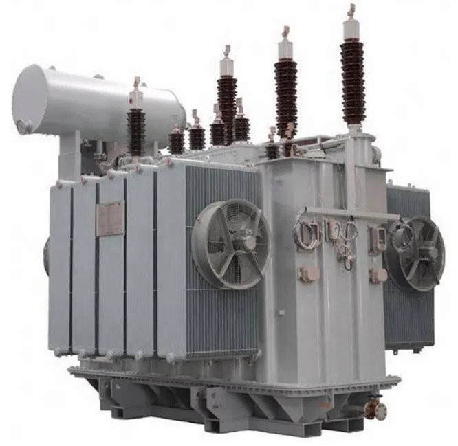
When power transformers are connected in parallel, the aim is to increase the overall capacity of the power system, provide redundancy, and ensure load-sharing among the transformers. However, successful parallel operation of transformers requires careful consideration of several factors.
1. Impedance Matching
Per Unit Impedance: The impedance of the transformers must be similar to ensure that the load is shared proportionally. If there is a significant difference, one transformer may carry more load than the other, leading to overheating or overloading.
Equal Impedance Ratio: For effective load sharing, the per-unit impedance (calculated on the same base) of the transformers should be as close as possible.
2. Voltage Ratings
Primary and Secondary Voltages: The voltage ratings on both the primary and secondary sides must match. If there is a mismatch, circulating currents can occur, leading to inefficiency and potential damage.
Voltage Ratio: The turns ratio (voltage ratio) between the primary and secondary windings of the transformers should be the same.
The difference in the no load terminal voltages of the transformers will cause a circulating current to flow between the transformers when paralleled. This current will flow at any load. The impedance of the circuit, which is usually the sum of the impedances of the transformers paralleled, limits the circulating current. The circulating current adds vectorially to the load current to establish the total current in the transformer. As a result, the capacity of the transformer to carry load current is reduced by the circulating current when the transformers are paralleled.
3. Phase Sequence and Phase Angle
Phase Sequence: The phase sequence of all transformers must be the same. If the phase sequence differs, it can result in short circuits or severe circulating currents.
Phase Angle Difference: The phase angle difference between the transformers must be zero. Any deviation can cause circulating currents, leading to inefficiency and potential damage.
4. Polarity
Correct Polarity: The polarity of the transformers must be the same to avoid phase opposition, which can cause the transformers to oppose each other's output and result in severe faults.
5. Tap Changer Settings
Uniform Tap Settings: If transformers have on-load tap changers, they should be set to the same position. Differing tap settings can cause circulating currents or unequal load sharing.
6. Load Sharing
Proportional Load Sharing: Assuming all conditions above are met, the transformers will share the load proportionally to their capacities and impedance ratings.
7. Cooling Systems
Consistent Cooling: The cooling systems of the transformers should be capable of handling the load. If one transformer has a less efficient cooling system, it might overheat and fail under heavy load conditions.
8. Protection Systems
Coordinated Protection: The protection systems, such as differential protection and overcurrent protection, should be coordinated to ensure they operate correctly in parallel operation.
9. Operational Issues
Inrush Current: When energizing transformers in parallel, consider the inrush current, which could lead to unnecessary tripping of protection devices.
By carefully considering these factors, transformers can operate efficiently and safely in parallel, ensuring reliable power delivery and system stability.
The load currents in the paralleled transformers will divide inversely to the impedances of the trans- formers paralleled. Generally, the difference in resistance has an insignificant effect on the circulating current because the leakage reactance of the transformers involved is much larger than the resistance. Transformers having different impedance values can be made to divide their load in proportion to their load ratings by placing a reactor in series with one transformer so that the resultant impedance of the two branches will create the required load sharing.
10. Delta–delta Connected Transformer
When delta–delta connected transformer banks are paralleled, the voltages are completely determined by the external circuit, but the division of current among the phases depends upon internal characteristics of the transformers. Considerable care must be taken in the selection of transformers, particularly single-phase transformers in three-phase banks, if the full capacity of the banks is to be used when the ratios of transformation on all phases are not alike. In the delta-Y connection, the division of current is not dependent to the differences in the characteristics of individual transformers.
