I. Introduction
In a previous post, the Impedance Method of Short-Circuit Calculation has been presented. To provide a comparative analysis on the accuracy of each calculation, the example provided in the impedance method will be used in this article.
Per unit value of any quantity is defined as the ratio of actual value to the chosen base value in the same unit.

Per Unit Impedance

where:


Change of Base
The impedances are usually specified on the rating of the equipment. These impedances need to be changed into PU values from the base of the equipment rating (old value) to that of the chosen system base (new value).


II. Example Calculation

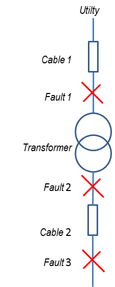
From Figure 1, given the parameters below, calculate the 3-phase fault and X/R ratio at Fault 1, Fault 2 and Fault 3:
- Utility
Available Fault = 436 MVA
X/R = 15 - Cable 1
Length = 1300 m
Unit Resistance = 0.39 ohms/km
Unit Reactance = 0.039 ohms/km
Number of parallel conductors / phase = 1 - Transformer
Primary Voltage = 13.8 kV
Secondary Voltage = 0.48 kV
Capacity = 2 MVA
%Z = 5.75%
X/R = 5.662 - Cable 2
Length = 500 m
Unit Resistance = 0.048 ohms/km
Unit Reactance = 0.029 ohms/km
Number of parallel conductors / phase = 2
Conversion of Actual Values to Per Unit
Choosing some arbitrary base values
MVAb = 2MVA
kVb = 13.8kV
At 0.48kV (Transformer Secondary Side):
MVAb = 2MVA
kVb = 0.48kV
From the above selected base values, the PU equivalent of actual values will be:
- Utility
Available Fault = 436 MVA
X/R = 15- PU values
- Zpu1 = 0.004587156 pu
- Rpu1 = 0.000305133 pu
- Xpu1 = 0.004576996 pu
- Cable 1
Length = 1300 m
Unit Resistance = 0.39 ohms/km
Unit Reactance = 0.039 ohms/km
Number of parallel conductors / phase = 1- PU values
- Zpu2 = 0.005351068 pu
- Rpu2 = 0.005324512 pu
- Xpu2 = 0.000532451 pu
- Transformer
Primary Voltage = 13.8 kV
Secondary Voltage = 0.48 kV
Capacity = 2 MVA
%Z = 5.75%
X/R = 5.662- PU values
- Zpu3 = 0.0575 pu
- Rpu3 = 0.010000644 pu
- Xpu3 = 0.056623645 pu
- Cable 2
Length = 500 m
Unit Resistance = 0.048 ohms/km
Unit Reactance = 0.029 ohms/km
Number of parallel conductors / phase = 2- PU values
- Zpu4 = 0.121702039 pu
- Rpu4 = 0.104166667 pu
- Xpu4 = 0.062934028 pu
Please note that the base kV for this cable is 0.48kV
III. Fault Calculations
From the above calculated PU values, it is now possible to calculate the short-circuit currents at the different fault locations.
Fault 1 (13.8kV)


From eq. 1


Calculating the current at Fault1 @ 13.8kV:


Fault 2 (0.48kV)


From eq. 1


Calculating the current at Fault2 @ 0.48kV:


Fault 3 (0.48kV)


From eq. 1


Calculating the current at Fault2 @ 0.48kV:


IV. Impedance Method vs. Per Unit Method
The results of the Impedance Method and Per Unit Method are the same hence the accuracy of Per Unit Method is comparable to the Impedance Method.
