There are different protection techniques and principles. Fuses are the simplest and cheapest technology. After operation, however, fuses are required to be manually replaced to restore protection features. Protection relays are applied if fuses are not feasible. There are different protection relays, require different inputs, and process the information differently, but the main objective of all protection relays is to correctly detect and clear a fault as quick as possible.
I. Fuses
Fuses were the first form of protection used on electrical networks over a hundred years ago. Fuse links are simple hence relatively cheap devices.
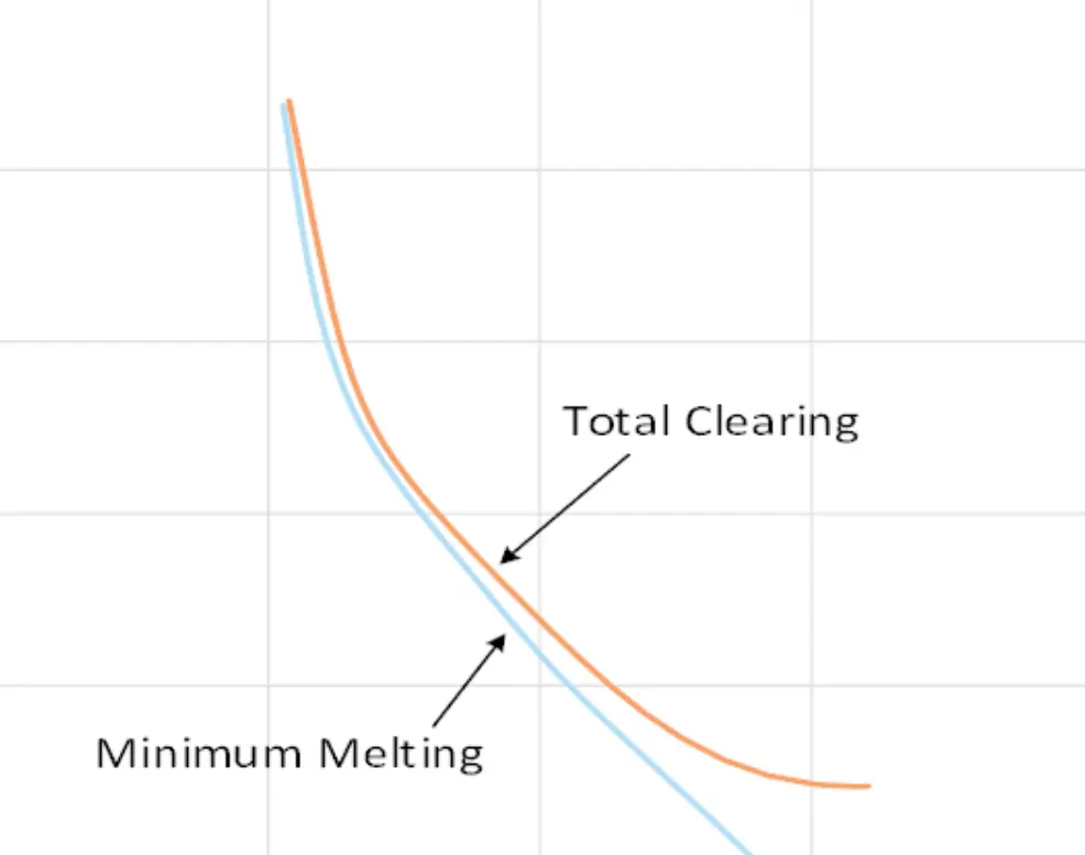
A fuses is a short piece of conducting material, with a cross-sectional area incapable of carrying currents beyond the permitted to flow in the protected circuit. The common type of fuses consists of a short conducting wire inside a casing, capable of carrying the current permitted for the protected zone. The cross-section and material of the wire determines the magnitude of current the fuse can conduct without melting. The wire will melt once the temperature increases caused by the current flowing through the fuse. The fuse wire melts once the temperature becomes higher than the melting temperature of the wire material.
The fuse can melt almost instantaneously or with some time delay. A melted fuse will need to be manually replaced, and this is one of the drawbacks of using fuses for protection.
II. Overcurrent Relay
An overcurrent relay have a current coil. When normal current flows through this coil, the magnetic effect generated by the coil is not sufficient to actuate the moving element of the relay, as the restraining force is greater than deflecting force. However, when the current through the coil increases, the magnetic effect increases, and after a certain level of current, the deflecting force generated by the magnetic effect of the coil, reaches the restraining force actuating the moving element to move towards the contact position on the relay. Although there are different types of overcurrent relays but basic working principle of overcurrent relay is more or less same for all.
Overcurrent relays operate with inverse time or definite time, and instantaneous characteristics. The relays have a set pick-up current, Is. When the current reaches and/or surpasses the current Is value, a timer starts. The relationship between the magnitude of the current and the time needed for tripping is inverse time or definite time. When the timer reaches its corresponding point on the time-current curve, without the current dropping, the relay will trip. The relay will trip instantaneously if the current reaches the instantaneous trip setting. The inverse curves are usually divided into normal, very or extreme inverse characteristics. ANSI and IEC have standards for the characteristics of these time-current curves (TCCs) which are commonly used, however the user may choose/create tailored characteristics.
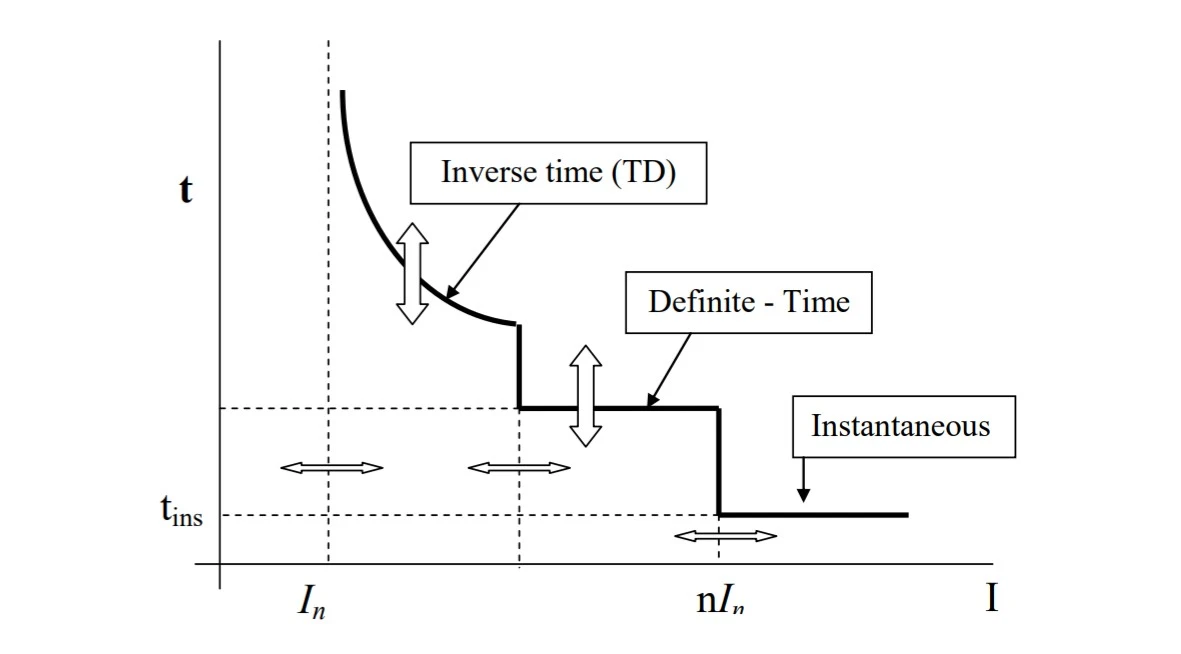
- Inverse Time
- Inverse time relays operate such that the operating time decreases as the magnitude of the fault current increases. This characteristic is useful for providing coordination between upstream and downstream protection devices.
- Definite Time
- Definite time relays operate after a preset time delay, regardless of the magnitude of the fault current. This characteristic ensures a fixed time delay before tripping, providing a clear and predictable operation time.
- Pickup Time
- Pickup time refers to the time taken by the relay to start operating after the fault current reaches or exceeds the pickup value (threshold). It is essentially the response time of the relay.
- Instantaneous
- Instantaneous relays operate without any intentional time delay when the fault current exceeds a certain threshold. These relays provide immediate protection and are used where fast tripping is required.
In applying inverse, time-delay, overcurrent relays is to choose the pickup setting, In (Figure 2) of the relay so that it will operate for all short circuits on the section or zone for which it is intended to provide protection. This is its primary function. The relay must be set so it will always operate for faults in that zone of protection. This will require margins above normal operating currents and below minimum fault currents.
The pickup setting should also provide backup for an adjacent line section or adjoining equipment. It should be noted, however, that the backup function of a protection relay is a secondary consideration. The primary function of protecting its own line section should not be compromised to provide this backup feature.
The disadvantage of overcurrent relays is the supply continuity which cannot be maintained at the load end in the event of fault. Time delay is provided but this is not desirable in the event of short circuits. Protection coordination is difficult and changes in settings is required with the addition of load.
Overcurrent protection is not applicable for long distance transmission lines where rapid fault clearance is necessary for stability. Relay have difficulties in distinguishing between fault currents at one point or another when fault impedances between these points are small, resulting to poor discrimination.
III. Directional Overcurrent Relay
Directional overcurrent protection is applied when it is necessary to protect the system against fault currents that could circulate in both directions through a system. Bidirectional overcurrent protection could produce unnecessary disconnection of circuits which can happen in ring systems, mesh systems, and as well as systems with multiple in-feed points.
Principle of Operation
The operating torque can be defined by

where:
Ф1and Ф2 are the polarising values, Ф1 being proportional to the current and Ф2 proportional to the voltage, with ϴ the angle between Ф1 and Ф2. The torque is positive if 0< ϴ <180◦, and negative if 180◦ < ϴ <360◦. It should be noted that ϴ is in phase with I but lagging with respect to the voltage since
")
If I and V are in phase, then the fluxes are out of phase by 90◦. Therefore, the angle for maximum torque occurs when the current and voltage of the relay are in phase. This can be obtained very simply by using the current and voltage from the same phase.
IV. Directional earth-fault relays
Directional earth-fault relays are designed based on the concept that the residual voltage (Vr) is equal to three times the zero-sequence voltage drop (V0) in the source impedance. The residual voltage is displaced with respect to the residual current (Ir) according to the angle characteristic of the source impedance.
Ideally, voltage transformers (VTs) are used to obtain the polarization voltage for directional relays. However, when suitable VTs are not available, current polarization can be employed. Current polarization involves using the earth current from a local transformer connected to earth. The principle behind this is that the neutral current always flows towards the system from earth.
Depending on the fault location, the residual current may flow in any direction. The relay must detect this direction and operate accordingly.
The possibility of voltage-polarized directional protection relay failure is minimal, hence it is recommended to use this arrangement wherever possible.
Further Reading
There are other types of protections relays which is beyond the scope fo this article. For further readings, please click here.