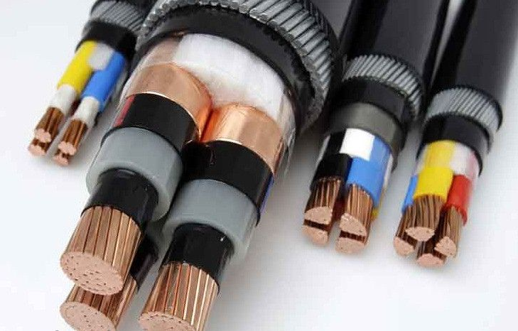
Multi-core cables are particularly used for control, instrumentation, computers and telecommunications. These cables carry very small currents in their conductors compared to power cables. These currents feed into very sensitive electronic circuits. The system design of these electronic circuits must take account electromagnetic interference (EMC) that can be induced into the multi-core cable conductors.
To mitigate EMC, screens are provided around on these mutli-core cables. The screens are grouped typically two, three or four conductors to discharge static charges that can otherwise accumulate and create noise or damage at the terminal equipment. Screens are also provided around all the conductors in the cable for a similar reason.
Stray Currents
If a screen is earthed at both ends of its cable then a 'stray' current may be caused to flow in the screen. The reason for this is, the earth potential at each end of the cable may not be exactly the same or both zero. A few millivolts difference due to stray currents, or worst fault currents, the local earthing system will cause interference the electronic signals.
The stray current flowing along the screen will magnetically induce currents into the core conductors. It is therefore common practice to earth the cable screens only at one end of the cable. The bonding of each screen is made at a specially designed 'clean earth' busbar mounted inside, for example, a control panel or marshalling box.
Power Cables
High voltage power cables above 3000 V are provided with graphite semiconducting screens at the surface of the conductor and on the outside surface of the insulation. The purpose of the screen around the conductor is to control the potential gradient, or electric stress, in the insulation that is close to the conductor. The high surface voltage is accompanied with a very rapid fall in potential just inside the insulation measured in volts/mm.
The natural insulating property of the insulating material is limited by the maximum potential gradient at any point within its structure. If the maximum gradient is exceeded then local breakdown and discharge will occur which is called "partial discharge". If this continue for a long time the insulation will eventually fail.
In a cable the stress is greatest at the surface of the conductor. This screen is not earthed. It must be bonded to the inner sur- face of the insulation very carefully so that no pockets or gaps exist, which could also promote local discharges.
A similar screen is placed around the outer surface of the insulation, especially with multi-core high voltage cables so as to maintain a radial stress pattern in each core. A metallic tape is placed over the semiconducting screen. The tape may be made of tinned copper, bronze or aluminium. The semiconducting screen is used to ensure a good electrical contact is made with both the insulation and the tape. This is necessary to avoid local highly stressed areas on the surface of the insulation, so that it is not weakened. The tape is usually bonded to earth at the switchgear end of the cable. At the switchgear the bonding will be taken to the internal earth busbar.
