Note: This is the first part of power system voltages and insulation coordination.
Insulation coordination is dealt with for three phase AC systems with nominal voltages Un > 1kV in IEC 60071. The insulation of equipment must be designed in such a way as to withstand all foreseeable voltage stresses or to limit the damage in insulation to the faulted equipment.
The voltage withstand capability of the insulation depends on shape, duration, height and frequency of the overvoltages that arise and on the insulation material. Insulation can be solid insulation (i.e. XLPE, PVC), liquid insulation (i.e. oil), gas insulation (i.e. air, SF6) or combinations of different kinds of materials (i.e. paper–oil insulation).
Voltage Withstand Capability
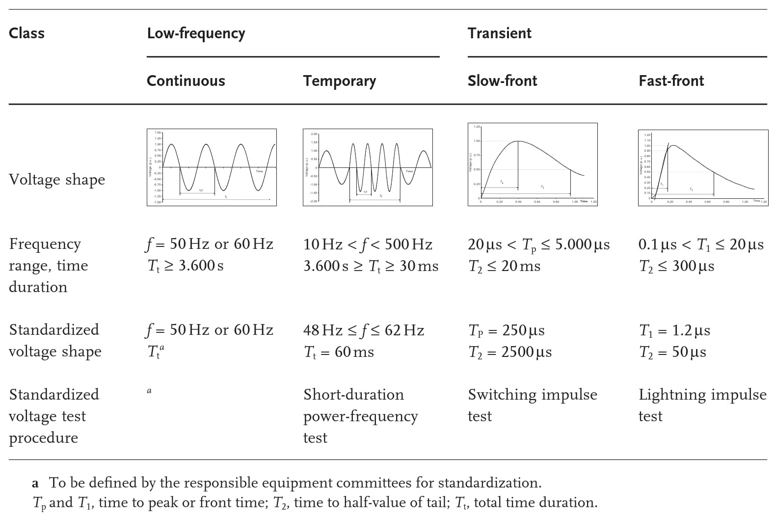
The voltage withstand capability is generally greater with shorter duration of the voltage stress. Voltages and overvoltages are classified according to their shape and duration. Continuous power frequency voltage with constant r.m.s. value, which may achieve at the most the values specified in IEC 60038.
Temporary overvoltage, which can occur in case of short-circuits (in power systems with low impedance neutral earthing) or ground faults (in power systems with resonance earthing or with isolated neutral). The duration can vary from some seconds (short- circuits) up to some hours (ground faults, resonances). The frequency of the temporary overvoltages can also be below or above the nominal frequency of the power system.
- Transient overvoltages
- With duration of a few milliseconds, immediately followed by temporary overvoltages. Normally the transient overvoltage occurs as highly damped overvoltage.
- Slow-front overvoltage
- Resulting from switching of capacitive and inductive currents, from long lines or as high-frequency AC voltages in the case of ground faults or short-circuits. Slow-front overvoltages are normally unidirectional, with a rise time to peak between 20 μs and 5 ms and a tail duration below 20 ms.
- Fast-front overvoltages
- Occur due to lightning strokes into phase conductors or due to backward flashover following lightning strokes in towers or earth conductors or can result from switching actions. Fast- front overvoltages are normally unidirectional; the time to peak is in the range 0.1–20 μs; the tail duration is below 300 μs.
- Very-fast-front overvoltages
- Result from operation of disconnecting switches within gas-insulated switchgear. They are normally unidirectional; the time to peak is below 0.2 μs; the total duration is less than 3μs. In most cases very-fast- front overvoltages have superimposed oscillations with frequency between 30 kHz and 100MHz.
The terms explained below are used for insulation coordination:
- External insulation.
- The air between contacts or live parts. The surfaces of solid insulation in contact with air, subject to dielectric stress or to the effects of atmospheric conditions such as pollution and humidity, also belong to external insulation. If external insulation is operated inside closed rooms, the insulation is called weather-protected otherwise it is called non-weather-protected.
- Internal insulation.
- The solid, gaseous or liquid parts of insulation or any combination of these parts protected from the effects of atmospheric conditions, for example, the paper–oil insulation (oil-impregnated insulation) of a transformer.
- Self-restoring insulation
- An insulation that completely recovers its insulating properties after a disruptive discharge in the insulation. Atmospheric or pressurized air, nitrogen and SF 6 are self-restoring insulating materials.
- Non-self-restoring insulation
- An insulation that loses its insulating properties completely or partly after a disruptive discharge. Synthetic materials such as XLPE or paper– oil insulation are of the non-self-restoring type.
- Withstand voltage
- The value of a testing voltage applied during the voltage withstand test, during which a defined number of disruptive discharges are tolerated . For the definition of the conventional assumed withstand voltage the number of disruptive discharges is equal to zero; this value is indicated in IEC 60071 for non-self-restoring insulation, and the withstand probability is equal to 100%.
- The statistical withstand voltage allows for a specified number of disruptive discharges during the test, which is equal to a defined withstand probability. The withstand probability for self-restoring insulation defined in IEC 60071 is 90%.
- Required withstand voltage
- The testing voltage the insulation must resist during a standard withstand voltage test. The coordination withstand voltage indicates the value of the withstand voltage which fulfills the selected criteria in each voltage class.
- Standard withstand voltage
- The standard voltage value which is used in a standard withstand voltage test. The standard withstand voltage is the rated value of the insulation for one or more required withstand voltages.
- Standard short-duration power-frequency voltage
- The sinusoidal voltage with frequency between 48 and 62 Hz in 50 Hz systems with total duration of 60 s. Standard voltage shapes are also the standard switching impulse voltage, an impulse voltage with time to peak of 250 µ s and a time to half-value of the tail (see Figure 1 for explanation) of 2500 µs , and the standard lightning impulse voltage , an impulse voltage with time to peak of 1.2 µs and a time to half-value of the tail of 50 µs .
- Rated insulation level
- The set of standard withstand voltages indicating the dielectric strength of the insulation.
- Standard insulation level
- The rated insulation level, the standard withstand voltages are associated with the highest voltage of equipment, which are given as recommended values in IEC 60071-1. The highest voltage for equipment is the highest phase-to-phase r.m.s.-voltage the equipment is designed for with respect to the insulation and other characteristics related to this voltage value in the relevant standards.
References
Power System Engineering
Planning, Design, and Operation of Power Systems and Equipment
Juergen Schlabbach and Karl-Heinz Rofalski