Introduction
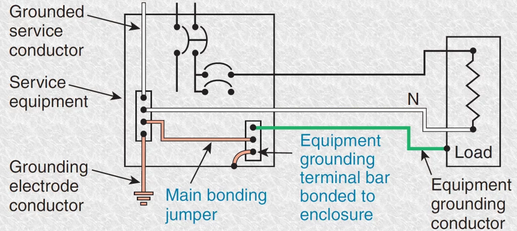
In power system, grounding or earthing means connecting frame of electrical equipment (non-current carrying part) or some electrical part of the system (e.g. neutral point in a star-connected system, one conductor of the secondary of a transformer etc.) to earth. This connection to earth may be through a conductor or some other circuit element depending upon the situation. Regardless of the method of connection to earth, grounding or earthing offers two principal advantages.
- Provides protection to the power system.
An example is the grounding of the neutral point of a star-connected system. If phase to earth fault occurs on any one line, a large fault current will flow through the overcurrent protective device such as a circuit breaker. The circuit breaker will open to isolate the faulty line. This protects the power system from the harmful effects of the fault. - Provides protection to people.
Ensures the safety of the persons handling the equipment. For example, if insulation fails, there will be a direct contact of the live conductor with the metallic part (i.e. frame) of the equipment. Any person in contact with the metallic part of this equipment will be subjected to a dangerous electrical shock which can be fatal. In this chapter, we shall discuss the importance of grounding or earthing in the line of power system with special emphasis on neutral grounding.
Grounding or Earthing
Grounding or earthing is defined as the process of connecting the metallic frame or non-current carrying part of electrical equipment or some electrical part of the system such as the neutral point in a star-connected system, one conductor of the secondary of a transformer etc. to earth.
Grounding or earthing if done systematically in the line of the power system, it can effectively prevent accidents and damage to the equipment of the power system and at the same time continuity of supply can be maintained. Grounding or earthing may be classified as :
- Equipment grounding
- Earthing of the non-current-carrying metal parts of the electrical equipment.
- System grounding
- Earthing some part of the electrical system e.g. earthing of neutral point of star-connected system in generating stations and substations.
Neutral Grounding
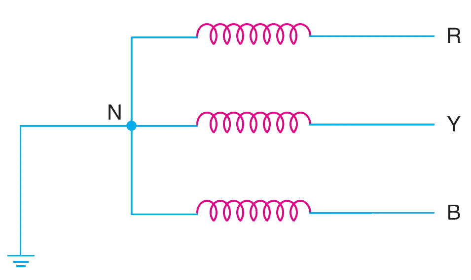
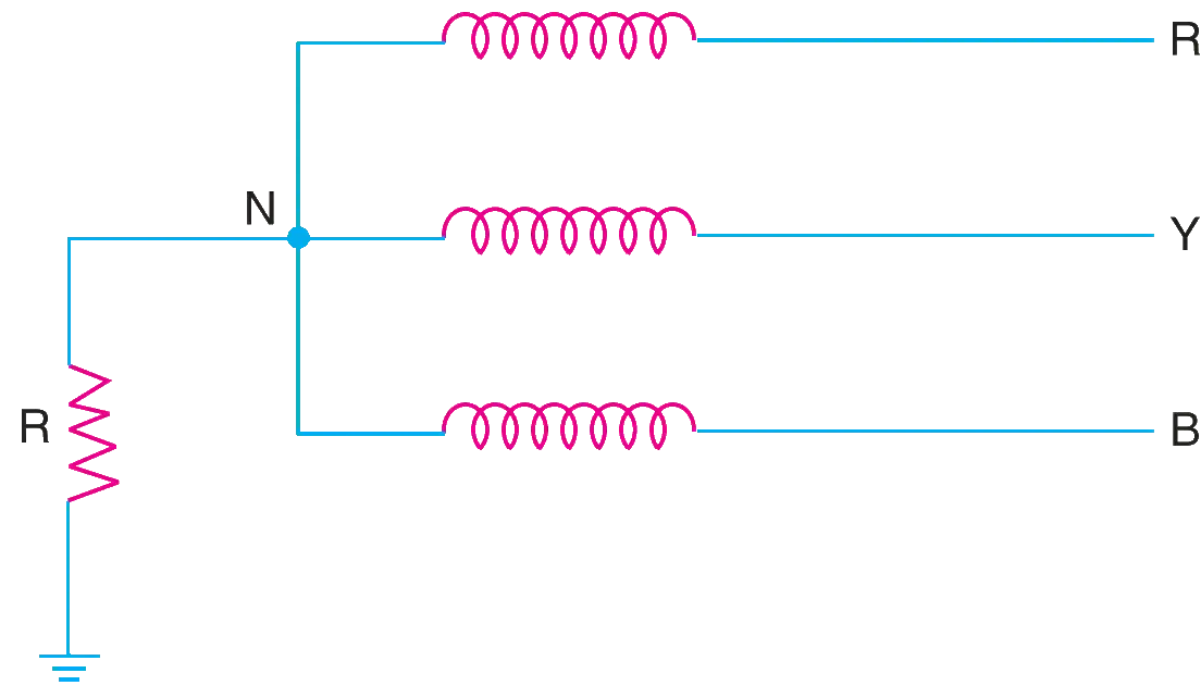
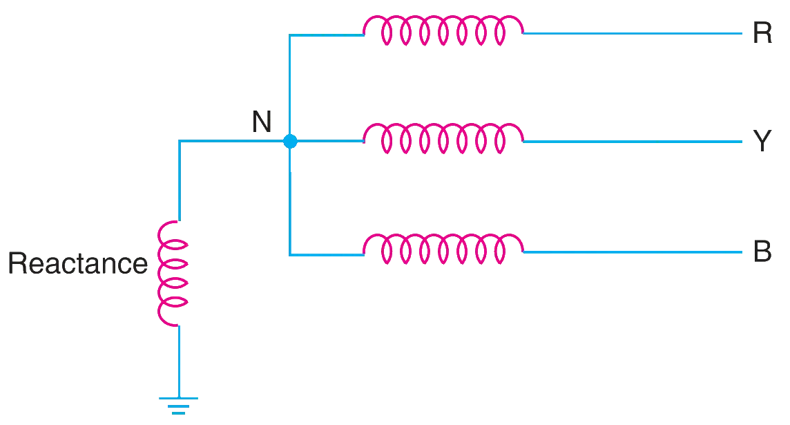
The process of connecting neutral point of 3-phase system to earth either directly or through some circuit element such as resistance or reactance is called neutral grounding. Neutral grounding provides protection to personal and equipment. It is because during an earth fault, the current path is completed through the earthed neutral and the protective devices operate to isolate the faulty conductor from the rest of the system.
Advantages of Neutral Grounding
The following are the advantages of neutral grounding :
- Voltages of the healthy phases do not exceed line to ground voltages i.e. they remain nearly constant.
- The high voltages due to arcing grounds are eliminated.
- The protective relays can be used to provide protection against earth faults. In case earth fault occurs on any line, the protective relay will operate to isolate the faulty line.
- The overvoltages due to lightning are discharged to earth.
- It provides greater safety to personnel and equipment.
- It provides improved service reliability.
- Operating and maintenance expenditures are reduced.
Methods of Neutral Grounding
The methods commonly used for grounding the neutral point of a 3-phase system are :
- Solid or effective grounding
- When the neutral point of a 3-phase system (e.g. 3- phase generator, 3-phase transformer etc.) is directly connected to earth through a wire of negligible resistance and reactance.
- Advantages
- Neutral is effectively held at earth potential.
- No arcing ground phenomenon or over-voltage conditions can occur.
- In an earth fault on any phase of the system, the phase to earth voltage of the faulty phase becomes zero.
- It is easier to protect the system from earth faults which frequently occur on the system.
- Disadvantages
- System instability due to frequently phase to earth fault partcularly in overhead system.
- Solid grounding results in heavy earth fault currents.
- Increased earth fault current results in greater interference in the nearby communication lines.
- Applications.
Solid grounding is usually employed where the circuit impedance is sufficiently high so as to keep the earth fault current within safe limits. This system of grounding is used for voltages upto 33 kV with total power capacity not exceeding 5000 kVA. - Resistance Grounding
- To limit the magnitude of earth fault current, it is a common practice to connect the neutral point of a 3-phase system to earth through a resistor.
- Advantages
- By adjusting the value of the resistor, the arcing grounds can be minimised.
- Earth fault current is small due to the presence of earthing resistance, hence, interference with communication circuits is reduced.
- IMproves system stability
- Disadvantages
- As the system neutral is displaced during earth faults, the equipment has to be insulated for higher voltages.
- System is costlier than the solidly grounded system.
- A large amount of energy is produced in the earthing resistor during earth faults making it difficult to dissipate.
- Applications.
It is used on a system operating at voltages between 2.2 kV and 33 kV with power source capacity more than 5000 kVA. - Reactance grounding
- In this system, a reactance is inserted between the neutral and ground. The purpose of reactance is to limit the earth fault current. By changing the earthing reactance, the earth fault current can to changed to obtain the conditions similar to that of solid grounding.
- This method is not used these days because of the following disadvantages:
- The fault current required to operate the protective device is higher than that of resistance grounding for the same fault conditions.
- High transient voltages appear under fault conditions.
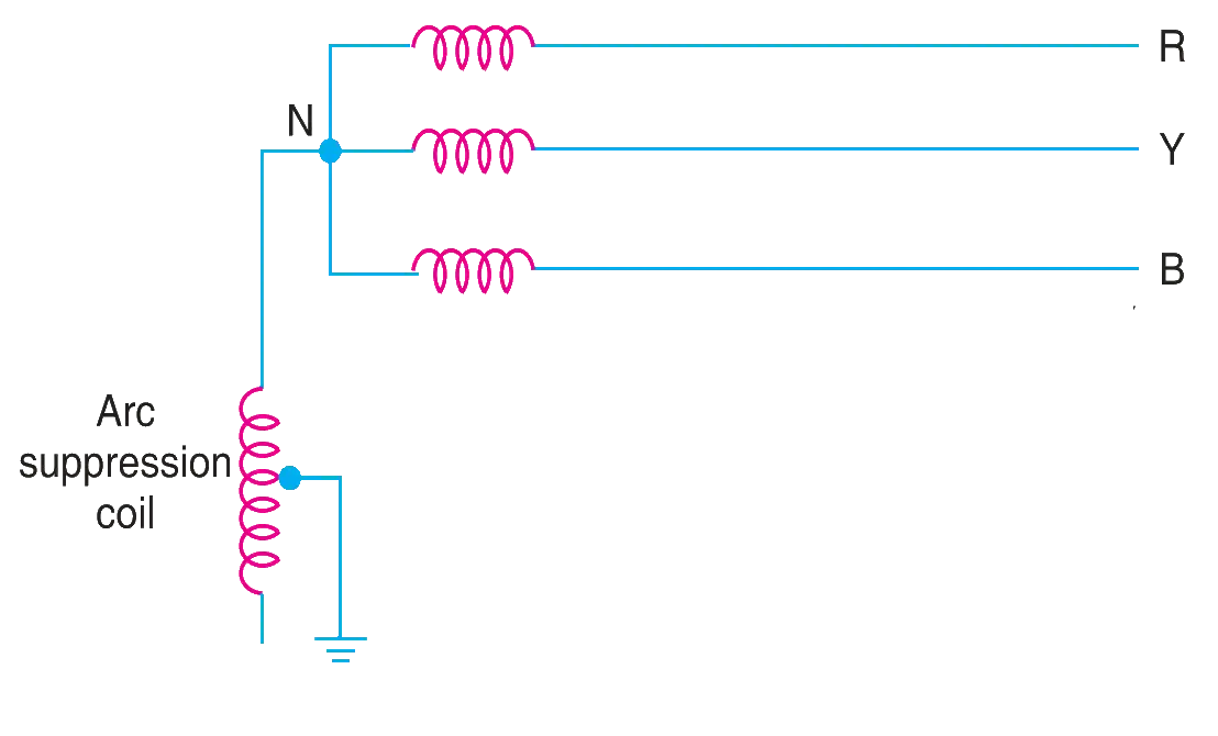
- Peterson-coil grounding
- This is also called arc suppression coil grounding or resonant grounding
- When the value of L of arc suppression coil is such that the fault current exactly balances the capacitive current.
- Advantages
- Completely effective in preventing any damage by an arcing ground.
- Has the advantages of ungrounded neutral system.
- Disadvantages
- Due to varying operational conditions, the capacitance of the network changes from time to time. Therefore, the inductance of Peterson coil requires readjustment.
- The lines should be transposed.
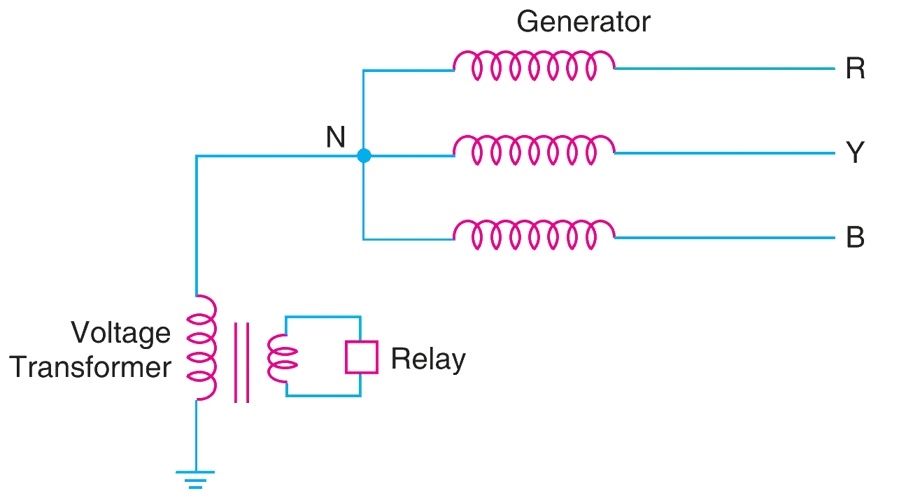
- Voltage Transformer Earthing
- In this method of neutral earthing, the primary of a single-phase voltage transformer is connected between the neutral and the earth. A low resistor in series with a relay is connected across the secondary of the voltage transformer. The voltage transformer provides a high reactance in the neutral earthing circuit and operates virtually as an ungrounded neutral system. An earth fault on any phase produces a voltage across the relay. This causes the operation of the protective device.
- Advantages
- Transient overvoltages on the system due to switching and arcing grounds are reduced.
- Has all the advantages of ungrounded neutral system.
- Arcing grounds are eliminated.
- Disadvantages
- The system insulation will be overstressed due the line voltage appears across line to earth capacitances during an earth fault on any phase.
- The earthed neutral acts as a reflection point for the travelling waves through the machine winding. This may result in high voltage build up.
- Applications.
The use of this system of neutral earthing is normally confined to generator equipments which are directly connected to step-up power transformers.
Recommendation
The choice of the method of grounding depends upon many factors including the size of the system, system voltage and the scheme of protection to be used.
