Copper Development Association – Supporting Electrical Engineers
The Copper Development Association (CDA) is a technical resource and non-commercial organization dedicated to promoting copper's superior electrical and mechanical properties. CDA provides expert guidance, technical support, and industry-leading information to engineers, designers, and specifiers working with copper and copper alloys. As part of the global Copper Alliance™, it bridges the gap between research and industrial applications.
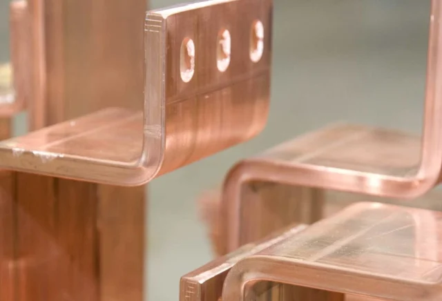
Busbars in Electrical Power Systems
Busbars are critical components in electrical power distribution, used to efficiently transmit current from a supply source to multiple circuits. Their applications range from vertical risers in multi-story buildings to distribution panels and large-scale industrial systems.
Key considerations in busbar system design include:
- Thermal Management – Limiting temperature rise due to energy losses.
- Energy Efficiency & Lifecycle Costs – Balancing conductor material use with operational efficiency.
- Short-Circuit Stresses & Protection – Ensuring mechanical and thermal stability during fault conditions.
- Jointing Methods & Performance – Optimizing bolted or welded connections for long-term reliability.
- Maintenance Considerations – Designing for durability and ease of inspection.
This guide provides essential information for designing efficient, cost-effective, and reliable busbar systems.
Thermal Considerations & Current-Carrying Capacity
All electrical systems experience energy losses, which manifest as heat. In busbar design, the maximum permissible operating current is primarily dictated by temperature limits, ensuring:
- Safe operation within thermal constraints.
- Preservation of mechanical integrity.
- Compatibility with support structures and cable terminations.
Section 2.0 Current-Carrying Capacity of Busbars outlines methods for estimating operating current and temperature, helping engineers optimize conductor sizing for performance and safety.
Energy Efficiency & Life Cycle Costing
Minimizing energy loss improves system reliability and reduces lifetime operational costs. While increasing conductor size raises initial material expenses, it significantly lowers long-term energy costs. Section 3.0 Life Cycle Costing explores these trade-offs, guiding engineers toward cost-effective design decisions.
Short-Circuit Effects & Mechanical Stability
Busbars must withstand substantial electrical and mechanical stresses during fault conditions. Key considerations include:
- Thermal rise during a fault event.
- Electromechanical forces causing deformation or mounting failure.
- Effects of harmonic currents leading to mechanical resonances.
These topics are discussed in 4.0 Short-Circuit Effects, emphasizing structural integrity and fault resilience.
Jointing Techniques for Long-Term Reliability
Busbar connections, whether bolted or welded, must be engineered for minimal resistance and high durability. Proper torque application on fasteners is critical, as a well-designed joint can exhibit lower resistance than an equivalent length of continuous conductor. Section 6.0 Jointing provides best practices for achieving reliable, low-loss connections.
Reference Data for Electrical Engineers
The guide book provides key reference materials on the electrical and mechanical properties of copper, equipping engineers with essential data for busbar design and performance evaluation.
