The size of a variable frequency drive (VFD) should be based on motor voltage and current and not on the torque or power rating. The voltage and full load current information can be taken from motor nameplate or datasheet.
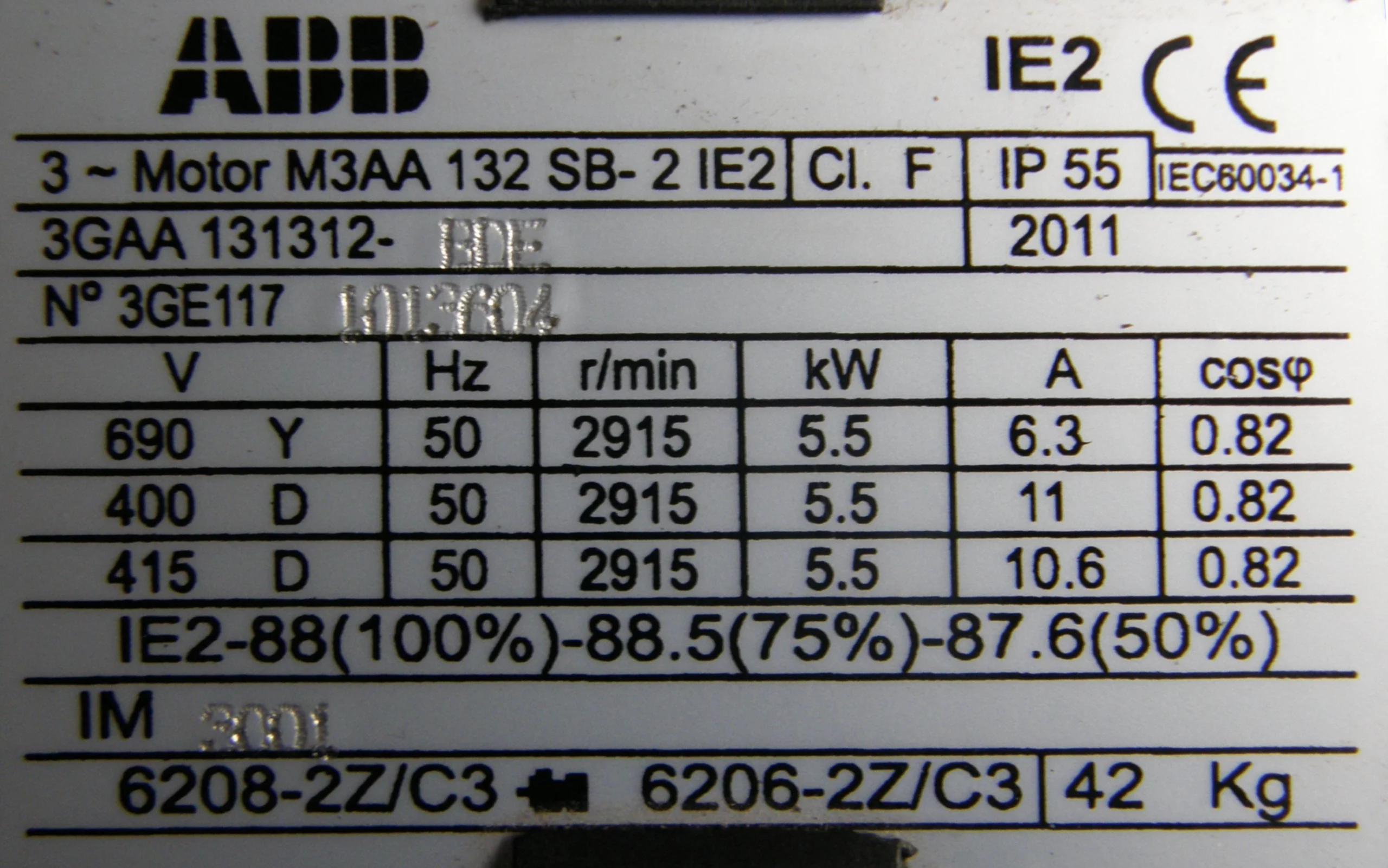
While the motor can be rated for more than one input voltage, the input voltage required for the particular application that is critical. VFDs are rated on design specific voltage range, hence, it is vital to assess the application for the amount of current it will draw and the speed at which it will be operating.
Calculations
The following equations help show the VFD power flow from AC to DC to AC to motor shaft power.
1. VFD Input Power (AC), PIN

Where:
PIN = AC input power to the VFD
IIN = AC input current to the VFD
VIN = AC input voltage to the VFD
PFIN = AC input power factor to the VFD
2. VFD DC Power (DC), PDC

Where:
PDC = VFD DC power
IDC = VFD DC current
VDC = VFD DC voltage
3. VFD Output Power (AC), POUT

Where:
POUT = VFD AC output power
IOUT = VFD AC output current
VOUT = VFD AC output voltage
PFOUT = VFD AC output power factor
4. Motor Shaft (Output) Power, Pshaft

Where:
Pmotor = Motor input power
Pshaft = Motor output power
ηmotor = Motor efficiency
Vmotor = Motor terminal voltage
Imotor = Motor current
PFmotor = Motor power factor
Equations (2) and (3) from the above equations are related to the VFD.Hence the equations can be summarized as

Examples will be provided in the next article.