This is Part 2 of the series of articles about three (3) phase Ac motor protection. Part 1 could be found here.
Overload Protection
Overload protection permits the motor to operate at its full capacity, but protects it from mechanical load abnormal conditions. High motor temperature causes deterioration of the insulation. When the motor is operated above the rated temperature rise, the motor windings would be damaged, however, for operation below it, the motor would last indefinitely.
The core and bearing losses of a motor comprise a low percentage of the total losses. It follows that the motor load current produces the motor copper losses is proportional to the motor temperature. This principle is the basis for the selection of overload relays.
Overload Relays
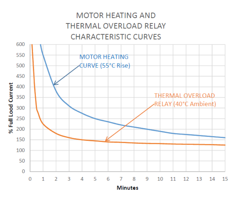
There are two (2) types of overload relays, thermal and magnetic. The thermal overload relay is designed so that its thermal capacity resembles the heat characteristic of the motor.
Thermal Overload Relays
Thermal overload relays are commonly the bimetallic type. The bimetal maintains its accuracy over a longer period of time and has automatic reset and adjustable characteristic features.
Magnetic Overload Relays
The magnetic overload relays are classified into two (2) general types, instantaneous and time-limit. Magnetic overload relays are generally of the time limit type. This type is less responsive to the motor current but usually applied to a specific condition of overloads such as a definite percentage of current and the time of its existence.
Instantaneous overload relays are similar to time-limit overload relays without the time-delay feature.
The main disadvantage of magnetic relays is their inability to compensate for repeated motor starts or temperature buildup in motors caused by fluctuating loads. Magnetic overload relays, however, are more accurate for definite current and time-overload conditions. Magnetic overload relays have a combination of time-limit and instantaneous trip features available in the market.
An application of the time limit magnetic re lays is on an air conditioning controller. Air conditioning motors are usually hermetically sealed type which differs from a conventional open cage motor. There is no service factor for these motors and their overload capabilities are very limited. This requires a relay with high accuracy and a short trip time on overload and locked rotor. The magnetic type relay is thus employed.
Selection of Overload Relays according to Type of Loads
The selection of overload relays to protect against excessive mechanical load is not simple. The load may be constant, fluctuating, or have a long time starting time. The constant load condition is normal for most electrical drives, thus it is very simple to select overload relays to provide the proper protection.
The practice for fluctuating loads is to adjust the thermal overload setting until the control does not trip under the fluctuating load. This is obviously the wrong approach. The safest approach is to determine by actual tests that the motor does not overheat during the maximum load cycle and then select the setting for the overload relays that will trip when over-temperature is reached. This setting is usually higher than that required for steady-state load conditions. Stalled rotor condition and single-phase protection will, however, be sacrificed to a certain extent.
Cooling Period - Overload Relay vs Motor
Another problem to which there really is no answer is that the overload relay cools more rapidly on the off-peak cycle than does the motor, due to the difference in mass. One possible solution would be to use two sets of overload relays for motor drives experiencing wide load fluctuations. One set of overload relays with an automatic reset feature could be selected to operate for a full load point. This could be used to operate an alarm or other warning devices. The second set of overload relays would be selected to operate above the full load point and would operate to shut down the equipment. This protection arrangement is mainly effective when the operator has control of the fluctuating load.
Loads With Long Acceleration Periods
Another type of load that is difficult to select for the overload relay is a blower due to its long acceleration period. Thermal overload relays have a tendency to trip the motor during acceleration several seconds after the motor has reached rated speed despite the current at this stage may be the full-load value or even less. The temperature increase of the overload relay heater coils may cause them to extreme heat up if the starting current persists. However, the operating temperature will lag several seconds behind the temperature of the overload heater coils resulting in possible tripping even after several seconds the motor current has been reduced to the normal value.
To correct this issue, the next higher-size heater may be used but will sacrifice running protection. The first method to solve this issue is to bypass the heaters during the starting cycle. This sacrifices starting protection, but provides proper running protection for the motor. A second method is to use two sets of overload relays. One size provides running protection and is shorted during starting, and the other size provides starting protection. This method is quite satisfactory, but the control circuit is more complex.
A simple and reliable method that prevents the overload relays from unnecessary operation during the accelerating period but provides adequate motor protection from overheating is to use of saturable reactors. Saturable reactors are constructed with a small air gap and applied in such a manner that the reactor iron core becomes saturated at currents above 200% full-load current, tending to keep the value of the current through the heater elements relatively constant as the motor current increases above this point. As the current falls below this point, the iron core becomes unsaturated and the reactor impedance becomes very large compared to that of the heater elements. With this method, the overload relay operating characteristics are extended on starting currents.