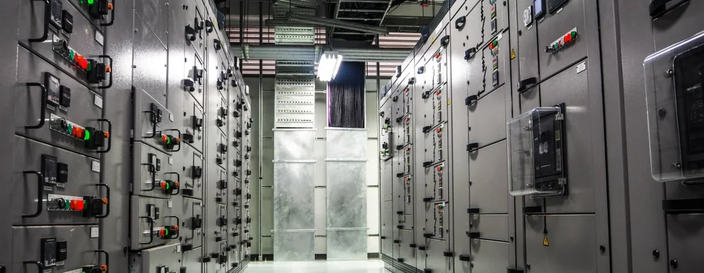
Short-circuit withstand ratings of a switchboard or motor control centre is a measure of its ability to withstand the dynamic and thermal stresses when a fault occurs within or near the equipment.
The r.m.s value of the short-circuit current at the switchboard or motor control center can be calculated from the parameters of the upstream supply equipment (i.e. transformers, cables, etc.). For determining the electrodynamic stresses, the value of peak current can be calculated by multiplying the r.m.s value of the short-circuit current by the factor n. The values for the factor n and the corresponding power factor are given in Table 7 IEC 61439-1 Low-voltage switchgear and controlgear assemblies Part 1: General rules.
| r.m.s Short Circuit Current, kA | cos φ | n |
|---|---|---|
| I ≤ 5 | 0.7 | 1.5 |
| 5 < I ≤ 10 | 0.5 | 1.7 |
| 10 < I ≤ 20 | 0.3 | 2 |
| 20 < I ≤ 50 | 0.25 | 2.1 |
| 50 < I | 0.2 | 2.2 |
| a Values of this table represent the majority of applications. In special locations, for example in the vicinity of transformers or generators, lower values of power factor may be found, whereby the maximum prospective peak current may become the limiting value instead of the r.m.s. value of the short-circuit current. | ||
This parameter is an important criterion into the selection of short-circuit withstand rating of a switchboard or motor control center to ensure that the switchboard or motor control center will not be damaged during the incident of a fault or short-circuit.
