There are times that the Electrical Engineer are unable to get the utility fault level data to calculate the required electrical parameters for a project. In such case, it is assumed that the utility fault level at the point of common coupling is an infinite bus. How will this assumption affects our design particularly the selection of electrical equipment? Will it be better to assume a fault level value other than an infinite bus?
An infinite bus is defined as an electrical supply with such large capacity that its voltage (and frequency, if AC) may be assumed constant, independent of load conditions. If a machine’s capacity is small relative to the electric supply system to which it is connected, it may be assumed to be operating on an infinite bus. The impedance of an infinite bus is nil making the voltage constant at any extent of load.
In ETAP, an infinite bus is considered as having the fault level of 100,000 MVA. Using this value, a comparative analysis was performed on the fault levels on several points of a typical utility connection as shown in figure below.
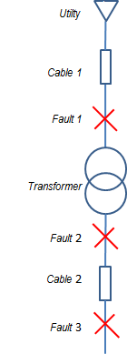
There are three fault locations considered:
F1 – at the primary of the supply transformer;
F2 – at the secondary of the supply transformer (Low Voltage);
F3 – at the incomer of switchgear (Low Voltage).
It is assumed that cables connect the utility supply to the transformer and the transformer to the switchgear. Impedances in all scenarios are considered constant.
Using 100MVA as the base value then setting the highest fault level value to be 500,000 MVA, which is 5 times the infinite bus capacity provided by ETAP, it could be seen that an increase of fault level:
- From 5000 MVA up to 500,000 MVA, the percent variance of fault current is 6% at the transformer primary, 1% in the transformer secondary and remains constant at the switchgear incomer.
- From 100 MVA to 500,000 MVA, fault current increased 300% at the transformer primary, increased 33% at the transformer secondary and 9% increased at the switchgear incomer.
| Fault MVA | Fault1 Fault Current, % | Fault2 Fault Current, % | Fault3 Fault Current, % |
|---|---|---|---|
| 100 | 0% | 0% | 0% |
| 250 | 108% | 18% | 5% |
| 500 | 200% | 25% | 7% |
| 1000 | 258% | 29% | 8% |
| 2000 | 284% | 31% | 9% |
| 5000 | 297% | 32% | 9% |
| 10000 | 300% | 33% | 9% |
| 50000 | 302% | 33% | 9% |
| 100000 | 302% | 33% | 9% |
| 500000 | 303% | 33% | 9% |
Using the result of the analysis in the above table, assuming an infinite bus at the primary side of the transformer will increase the fault current by about 33% at the low voltage transformer secondary. Using an infinite bus in the calculation of fault current significantly increase of equipment cost but will provide insurance that selected equipment ratings will be suitable for the application. It will also future proof the installed equipment from any increase capacity and fault MVA of the utility.