Excel is a very powerful and versatile tool. Its usage is only limited by your imagination. This tool is readily available on any computer in the office or at home. It is even found in most portable devices.
Power System Analysis Software
Not all projects are capable of acquiring a power system analysis software nor the services of companies specialized in power system simulations. With this scenario, the engineer needs to use whatever tool is available at his/her disposal. In this case, Excel tops the list.
Several tutorials has already been discussed on how to create time-current curves in excel. A pdf version was also published detailing the process of creating time-current curves in Excel.
Low Voltage Motor Protection
Electric motors are among the most commonly used electrical equipment. At home, this electrical equipment is everywhere. An electric fan, air conditioner, microwave oven, washing machine, personal computers, water pump, and many more home appliances use this electrical equipment. A fuse or circuit breaker alone could not fully protect this electrical equipment. Protections for thermal overloads, undervoltage and overvoltage are an examples of additonal protection for motors. For three (3) phase motors, single phase and phase reversal are also used.
Motor Protection Relay
Modern numerical motor protection relays are usually sufficient to meet all protection requirements of any one of the vast range of motor designs. Many motors designs do not tolerate overloads. A motor protection relay will have the following set of characteristics:
- extended start relay protection
- loss-of-load relay protection
- number of starts limitation
- stalling relay protection
- short circuit relay protection
- thermal relay protection
- earth fault relay protection
- negative sequence current detection
- winding RTD measurement/trip
- under-voltage relay protection
- auxiliary supply supervision
In this case study, we will be using the COMECA Gemstart5 motor protection relay.
GemStart5 is the next generation of the highly successful GemStart family of intelligent controller products brought to you by COMECA. It provides a completely new range of modular units that enables the user to choose the level of complexity they require for their application. This can range from a standalone, single unit for status monitoring, to a fully extended control and monitoring solution, integrated into a high-level control system.
Its primary purpose it to control, protect and monitor important Medium and Low voltage (MV/LV) loads used in process applications, such as motors, valves, and variable speed drive units.
The Gemstart5 can also be easily integrated into electrical distribution installations to monitor and control various electrical supplies, including MV/LV feeders, circuit breakers and other general-purpose supplies.
It also has great flexibility in that you can incorporate GemStart5 units into a control scheme with relative ease, as multiple devices may be connected on a single communications link with options on three communications protocols: Modbus; Profibus DPV1; and Gembus (proprietary protocol);. All three come pre-loaded and are individually selectable.
Motor Load
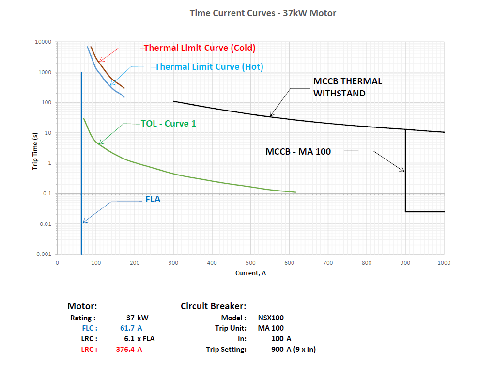
The motor to be protected in this case study is a 37kWv motor driving a pump. The motor has the following electrical characteistics:
Rating : 37 kW
FLC : 61.7 A
LRC : 6.1 x FLC
LRC : 376.4 A
The upstream breaker is a Schneider Electric NSX100F with MA100 electronic trip unit.
A Core-balance current transformer is also utilized to protect the motor from earth faults.
Thermal Overload Curves
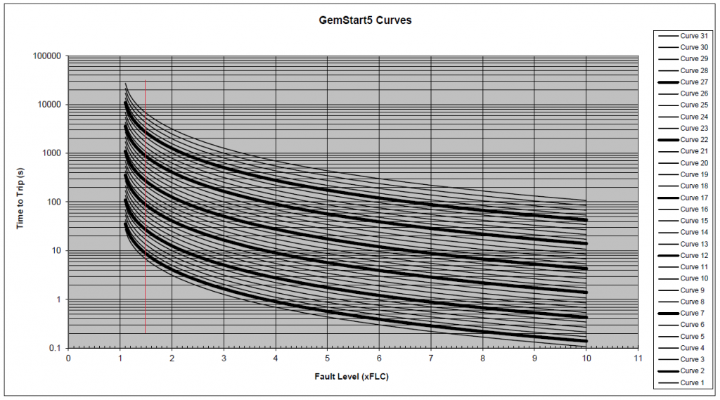
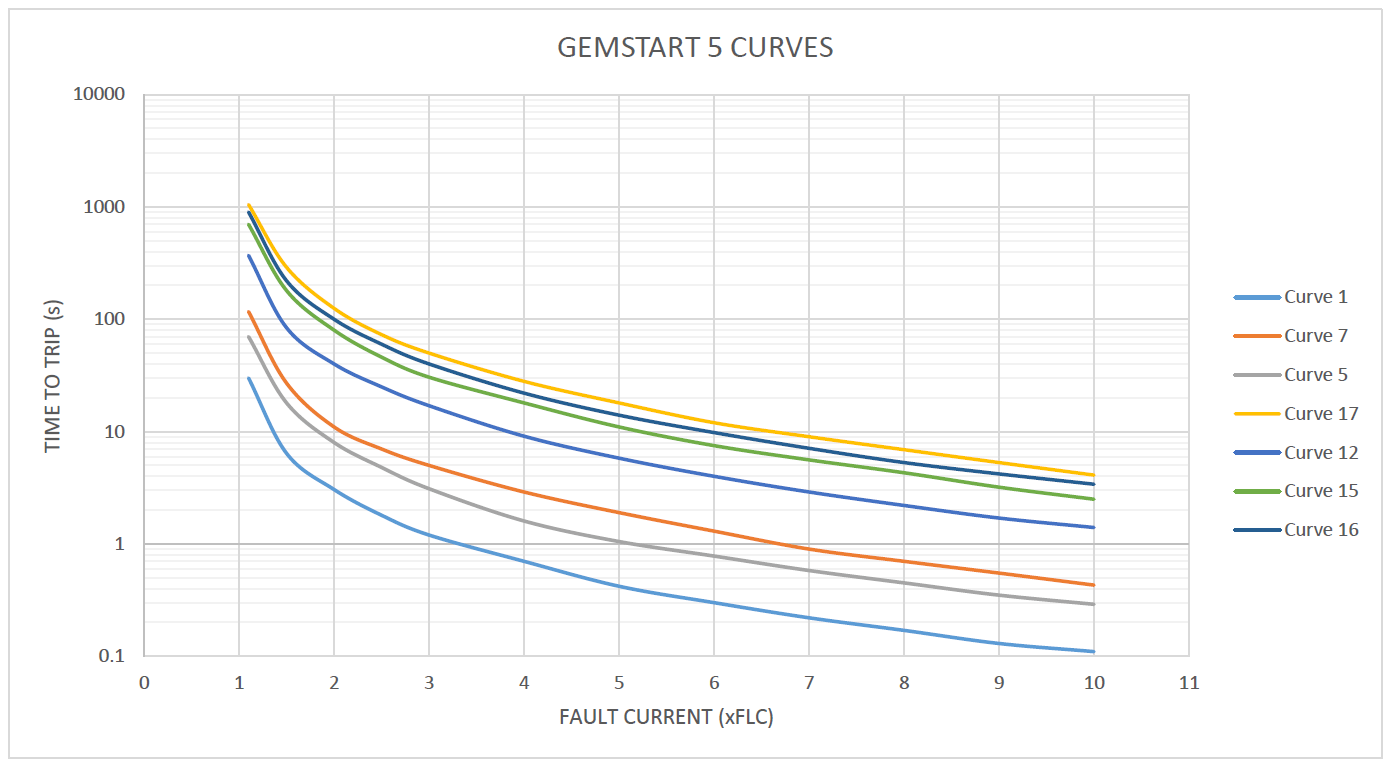
The COMECA Gemstart 5 Thermal overload curve is provided in the user manual.
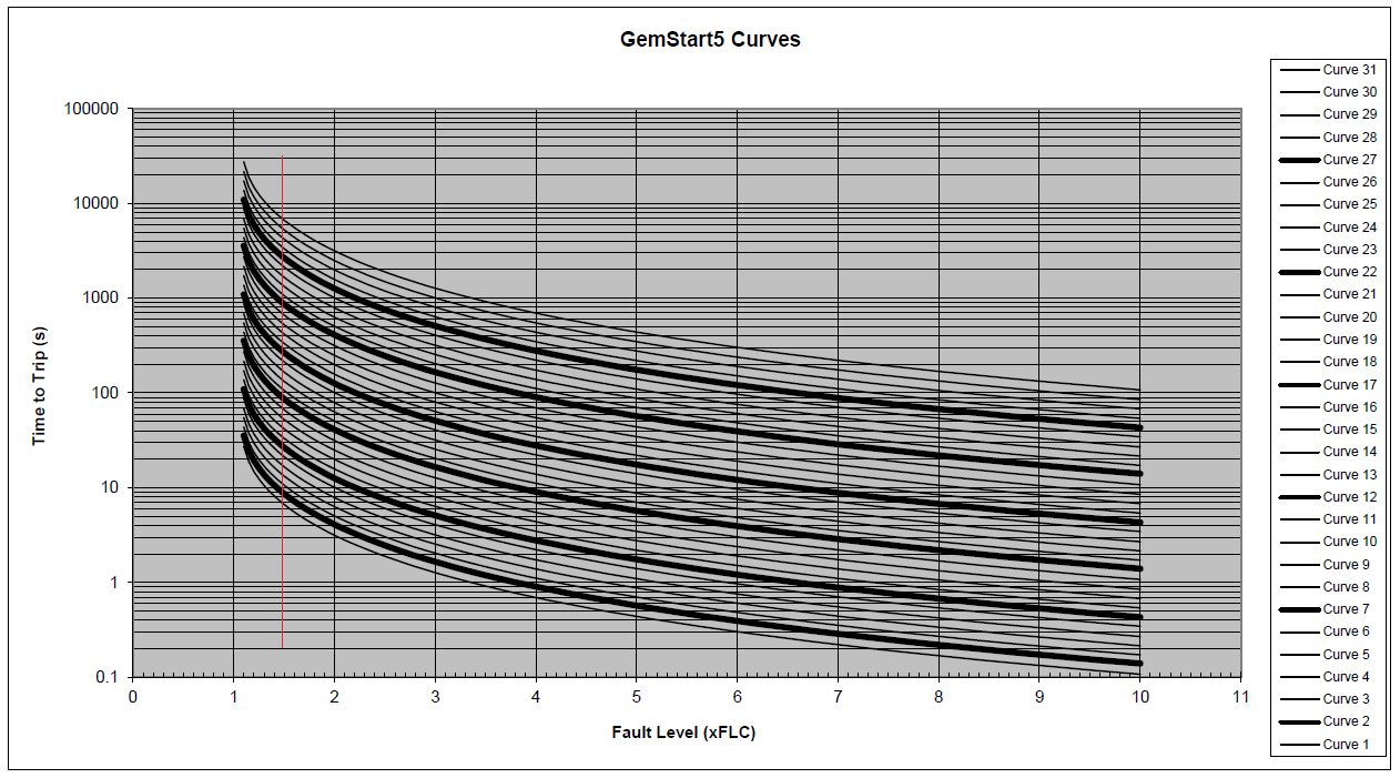
As Excel will be used to perform the coordination, the thermal overload curves need to be plotted in excel.
In addition, the circuit breaker time-current curve needs to be plotted as well. Please note that the horizontal axis needs to have a common unit for the Gemstart5 thermal overload curve and the circuit breaker TCC.
Thermal Overload and Circuit Breaker Time-Current Curves