
1. Introduction
Circuit breakers are critical components in power systems, providing rapid fault isolation to prevent cascading failures. However, their effectiveness depends on a properly functioning trip circuit—a failure in this circuit can render a breaker inoperative at the most crucial moment. Trip Circuit Supervision (TCS) is an essential monitoring function designed to ensure the trip coil, control wiring, auxiliary contacts, and power supply remain intact and ready to operate.
This article explores the importance, implementation, and best practices of TCS, along with recommendations for relay configurations and compliance with international standards.
2. Why Trip Circuit Supervision is Critical
2.1. Common Failure Modes in Trip Circuits
Trip circuit failures can arise from multiple causes, including:
- Open circuit in trip coil wiring – Broken or disconnected wires prevent breaker tripping.
- Loss of DC control voltage – Failure in the DC supply (typically 110V or 220V DC) can disable trip operation.
- Auxiliary contact failure (52a/52b) – Incorrect status feedback may lead to misinterpretation of breaker health.
- Contactor or relay malfunction – Interruption in trip relay operation can prevent tripping.
2.2. Consequences of a Faulted Trip Circuit
A breaker that fails to trip in response to a fault can result in:
- Severe equipment damage due to prolonged fault currents.
- System instability and blackouts in interconnected networks.
- Safety hazards due to arcing and overheating.
By continuously monitoring the trip circuit, TCS detects these failures early, allowing preventive maintenance before a fault event occurs.
3. Implementation of Trip Circuit Supervision
3.1. Typical Wiring and Connection Points
A TCS relay is connected to key points in the circuit breaker trip circuit to monitor for abnormalities. The diagram below illustrates a standard trip circuit supervision setup:
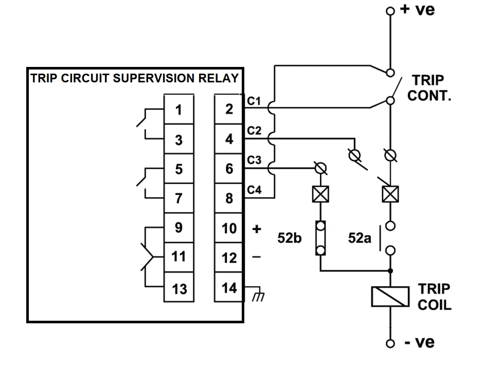
Key Monitoring Points:
- Trip Coil (TC1, TC2) – Ensures the coil is not open-circuited.
- DC Supply (110V/220V DC) – Monitors the integrity of the control voltage.
- Auxiliary Contacts (52a/52b) – Provides breaker status feedback.
- Alarm Connection to SCADA/RTU – Generates alerts for trip circuit failures.
3.2. Recommended Relays for TCS
Several protection relays incorporate TCS functionality, including:
- Siemens 7PJ13 – Dedicated trip circuit supervision relay.
- ABB REU615 / COM600 – Integrated into protection relays.
- Schneider MiCOM P40 Series – Provides trip circuit supervision with advanced logic.
- GE Multilin 850 / 869 – Includes customizable TCS settings.
- SEL-751 / SEL-710 – Configurable trip circuit supervision with SCADA integration.
3.3. Relay Configuration for TCS
The following settings should be applied when configuring a TCS relay:
- Enable Continuous Trip Circuit Supervision – Monitors trip coil resistance, wiring integrity, and supply voltage in real-time.
- Set Alarm Thresholds for DC Voltage – Detect low control voltage (e.g., <80% of nominal).
- Breaker Position Feedback – Use 52a/52b auxiliary contacts to cross-check breaker state.
- SCADA Integration – Send trip circuit failure alarms to the control system using IEC 61850 GOOSE messaging or hardwired signals.
4. Best Practices for Engineers
4.1. Monitor Both Trip Coils (If Available)
- Some breakers have dual trip coils (TC1 and TC2) for redundancy. Supervise both to ensure full breaker operability.
4.2. Use Continuous, Not Periodic, Supervision
- Some relays only test the trip circuit during breaker close operations. Instead, configure the relay for continuous supervision to detect failures immediately.
4.3. Integrate with SCADA and Alarms
- Trip circuit failures should trigger real-time alarms in SCADA or hardwired annunciators for immediate response.
4.4. Monitor DC Control Voltage
- A drop in DC supply voltage (<80% of nominal) can lead to unreliable tripping. Set under-voltage alarms accordingly.
4.5. Perform Routine Testing and Maintenance
- Regularly test the TCS relay and trip circuit integrity to verify proper operation.
- Simulate trip circuit faults to confirm relay response.
5. International Standards for Trip Circuit Supervision
To ensure compliance and reliability, TCS implementations follow established international standards:
| Standard | Description |
|---|---|
| IEC 60255-1 | General requirements for relays, including trip circuit supervision. |
| IEC 61850 | Communication standard for substation automation, including TCS alarms. |
| IEEE C37.90 | Protective relay standard, covering trip circuit monitoring functions. |
| IEC 60694 / IEC 62271-1 | High-voltage switchgear and controlgear standards that include TCS requirements. |
6. Conclusion
Trip Circuit Supervision is a critical function for ensuring circuit breaker reliability in high-voltage power systems. By continuously monitoring trip coils, DC voltage, and auxiliary contacts, TCS helps prevent catastrophic failures and improves overall system security.
For engineers designing protection schemes, implementing proper TCS relay settings, integrating alarms with SCADA, and adhering to IEC/IEEE standards is essential to maintaining a robust and fail-safe power system.