The majority of textbooks disregard open circuits when presenting unbalance faults in a power system. Almost always, only short-circuit faults are considered.
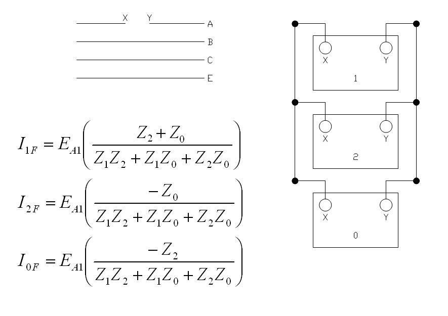
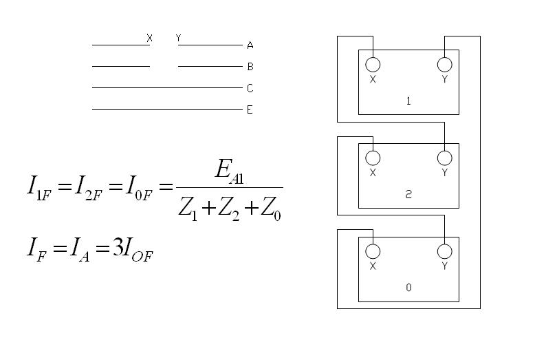
In the following circuit diagrams, it is assumed that the lines were opened between points X & Y.
Legend:
Va1 = Line to neutral voltage
I1F = Positive sequence fault current
I2F = Negative sequence fault current
I0F = Zero sequence fault current
Z1 = Positive sequence impedance
Z2 = Negative sequence impedance
Z0 = Zero sequence impedance


It is noticeable that the 2 lines open fault network sequence diagram is similar to the 1 line to ground fault. The only difference is the polarity of connection. The resulting formula however will be the same.
Reference:
Electrical Transmission & Distribution Reference Book - Westinghouse Electric
