Secondary Grounding
When a wye connected circuit and solidly or effectively grounded neutral is used, the following benefits are obtained in addition to the dual voltage capability,
(a) A single line-to-ground fault will cause sufficient ground current to flow to actuate standard protective relays and thereby isolate the faulted circuit, and identify the source of trouble,
(b) The maximum voltage to ground imposed upon any phase is limited to line-to-ground value, even when a ground occurs on one phase.
Ungrounded Operations
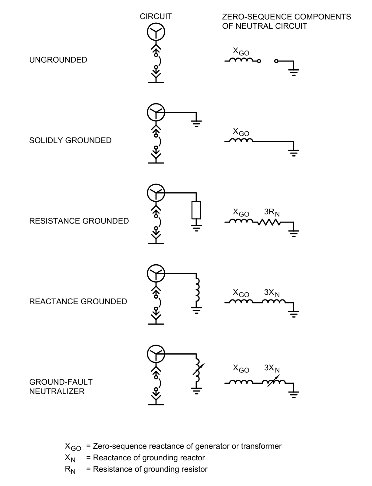
Ungrounded operation of generators and transformers will limit line-to-ground fault current to very small values. However, it has major disad vantages in that excessive overvoltages can exist on the system and locating ground faults may be difficult. For more details on this important problem, sce IEEE 142 "Grounding of Industrial Power Systems."
With an ungrounded delta secondary, a single line-to-ground fault will cause practically no ground current to flow and service continuity is maintained to the grounded apparatus. However, the ground will likely remain undetected unless ground-detector equipment is used, or unless a second ground fault occurs on another phase.
In the first case the location of grounds can only be found by successive opening of breakers until the ground is removed or by special ground-fault- locating equipment. In the second case a complete outage will occur and the grounds must be located by successive closing of breakers (or replacement of fuses).
Another drawback of the ungrounded system is the possibility of transient overvoltages in the event of an intermittent ground fault. Due to circuit inductance and capacitance, an intermittent ground fault can produce sufficiently high voltage to ground on the system to cause other ground faults.
If it is necessary to maintain service after the first line-to-ground fault, high-resistance grounding has advantages over operating ungrounded. A grounding resistor is selected equal to or less than the ohmic value of system capacitance to ground (1/3 of Xco). Ground-fault relaying is used to indicate the presence of a ground.
