1. Generator Motor Starting Capability
It is the task of Electrical Engineers to ensure that a selected generator is capable of supplying the motor starting requirements of a power system. NEMA MG-1 - Standard for Motors and Generators provides a recommendation for evaluating the motor starting capability of a synchronous generator, exciter, and regulator system.
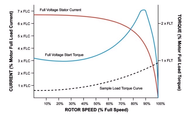
Prior into delving further into motor starting capability of a generator, we need to understand the starting characteristics of an induction motor. Induction motors normally has a starting current which is six (6) times its full load current on a direct-on-line method of starting. In addition, as per NEMA MG-1, the starting power factor will be 0.3 lagging or even less.
2. Generator Voltage Regulation
When a generator is subjected to a sudden load change there will be a resultant time-varying change in terminal voltage. This change in terminal voltage will be detected by the generator voltage regulator and will vary the field excitation as required to restore the terminal voltage. The maximum transient deviation in output voltage that occurs is a function of
- the magnitude, power factor, and rate of change of the applied load;
- the magnitude, power factor, and current versus voltage characteristic of any initial load;
- the response time and voltage forcing capability of the exciter-regulator system; and
- the prime mover speed versus time following the sudden load change.
Transient voltage performance is therefore a system performance criterion involving the generator, exciter, regulator, and prime mover and cannot be established based on generator data alone.
In selecting generators, the maximum transient voltage deviation or voltage dip caused a sudden increase in applied load is often specified or requested. When specified by the purchaser, the generator manufacturer should furnish expected transient voltage regulation, assuming either of the following criteria applies:
- Generator, exciter, and regulator furnished as integrated package by the generator manufacturer
- Complete data defining the transient performance of the regulator (and exciter if applicable) is made available to the generator manufacturer
When furnishing expected transient voltage regulation, the following conditions should be assumed unless otherwise specified:
- Constant speed (rated)
- Generator, exciter, regulator initially operating at no load, rated voltage, starting from ambient temperature
- Application of a constant impedance linear load as specified
3. Equations
In the absence of manufacturers' published information, the value of voltage dip may be estimated from machine constants, subject to the conditions set forth in NEMA MG-1 Section 32.18.1 and the following:
- Voltage regulator response time < 17 milliseconds
- Excitation system ceiling voltage* > 1.5
- Rated field voltage
")
Where:
Voltage dip, %
X'd= direct axis transient reactance, per unit
XL= applied load, per unit on generator kVA base or
")
Where:
KVArated = Generator KVA rating
KVAstarting = Load KVA during motor starting
Data estimated in accordance with the above calculation should be identified as "Calculated Voltage Dip."
Substituting the eq.(2) in eq.(1)
 + X{prime}_d}}%~~~right~~~(3)")
}~~~right~~~(4)")
4. Sample Calculations
Table 1 is a typical manufacturer's motor data.
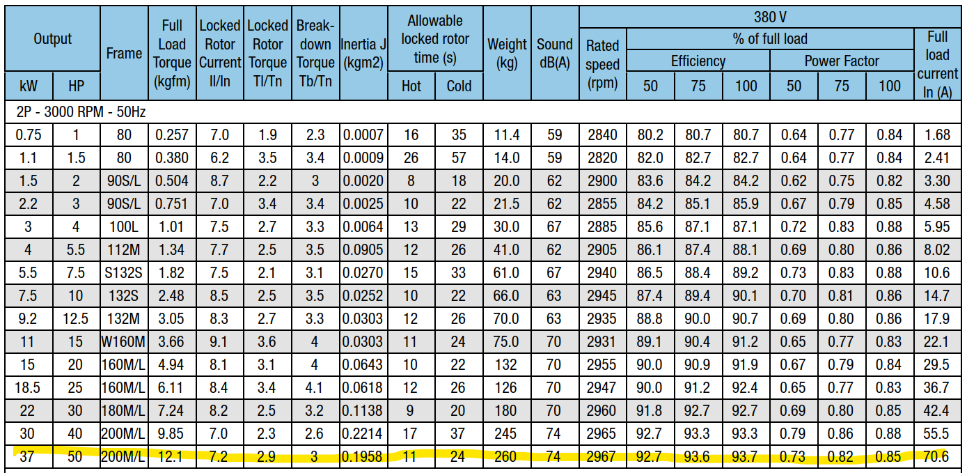
From the above table, considering a 37kW motor as the largest motor within the power system.
Output Rating = 37 kW
Full Load Current = 70.6 A
Locked Rotor Current Ratio (Starting Current / Full Load Current) = 7.2
The starting KVA of the 37kW motor at 380V using an across the line starting is
} = sqrt{3}*{380/1000}*(7.2*70.6)")
} = 334.6~KVA")
Another assumption that we need to consider is the demand on the generator on a normal operation without the 37kW motor.
Demand = 150 kVA
The total load with motor starting is
334.6 + 150 = 484.6 KVA
Typical generator reactances are shown Table 2.
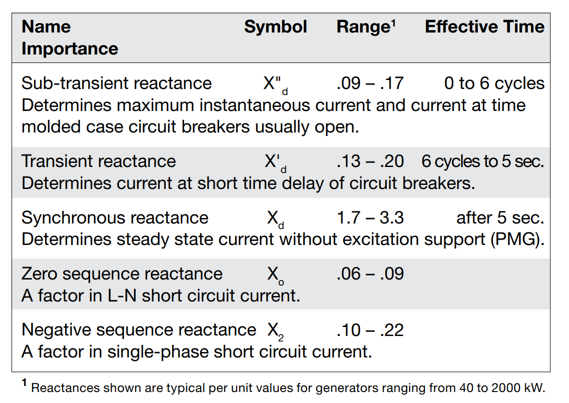
As the generator transient reactances (X'd) provided in Table 2 are within a range, for purposes of this example, we select
X'd = 0.19
The allowable voltage dip during motor starting is 15% at the motor terminal. Hence, the voltage dip at the generator terminal will be lower. Let us assume the
Voltage dip = 10%
Substituting the above values in eq. (4)
}")
}")

Using a standard size generator, we could select a 850 KVA generator for the purpose.
5. Final Thoughts
The sample calculations provided herein is beyond the ideal power system. A 37kW motor is not usually started direct-on-line but using a reduced voltage starting method such as Delta-Wye starter or part-winding starter. Moreso, the largest motor is always started first prior to any other loads in the power system.
The main purpose of this article is to illustrate that a generator size can be calculated using the motor starting characteristics.