Common-mode voltages are a common phenomenon when variable speed drives (VSD) are employed to control motors. There are many advantages of using VSDs in motors. Speed/torque control, and power consumption reduction are a few of the numerous lists. However, there are also disadvantages that users need to be aware of. The effects of common-mode voltages are one of the disadvantages that need to be managed even during the design stage.
I. Common Mode Voltages: Causes
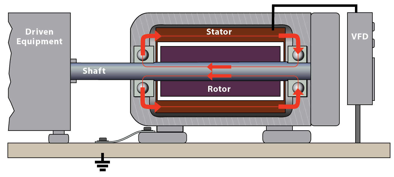
Alternating current (AC) motors operated using variable speed drives (VSD) use pulse width modulation (PWM) to control the speed of the motor. Pulse width modulation (PWM) capacitively induces voltage onto the shaft of the motor. This induced voltage is called common-mode voltage. Common mode voltage can discharge in the motor's bearings causing electrical discharge machining (EDM) pitting, frosting, and fluting damage which results in unplanned downtime and repair costs. Large motors over 100 HP (75 kW) and medium voltage motors may also have high frequency circulating currents which can also cause EDM pitting, frosting, and fluting damage. Direct current (DC) motors on drives may also have capacitively induced shaft voltage which can discharge in the motor's bearings [1].
The pulse width modulation (PWM) in variable speed drives (VSD) produces high-frequency harmonics which causes an increase in the magnitudes of leakage currents in the motor due to a reduction in the capacitive reactance of the winding insulation at higher frequencies[2].
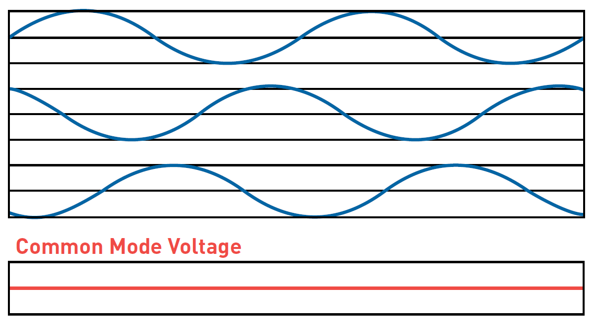
Source: mtecorp.com
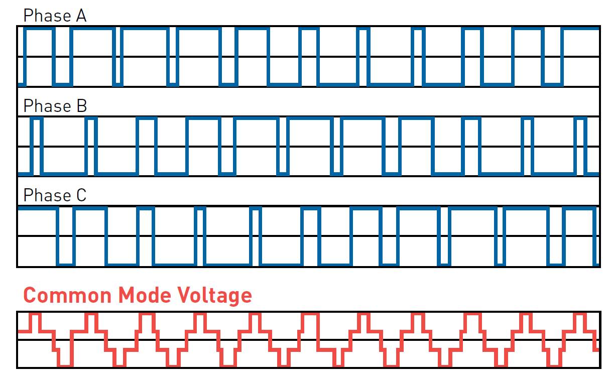
Source: mtecorp.com
Another cause of potentially destructive bearing currents which occasionally occurred in induction motors of all sizes operated by variable speed drives (VSD) is that the drives can become generators of a common-mode voltage which shifts the three-phase neutral potentials significantly from the ground. This common-mode voltage oscillates at high frequency and is capacitively coupled to the rotor which can result in peak pulses as high as 10-40 volts from the motor shaft to the ground.
II. Common Mode Voltages: Effects
Common-mode voltages induce voltages on the motor shaft which can result in the flow of destructive currents through motor bearings, manifesting themselves through pitting of the bearings, scoring of the shaft, and eventual bearing failure[2].
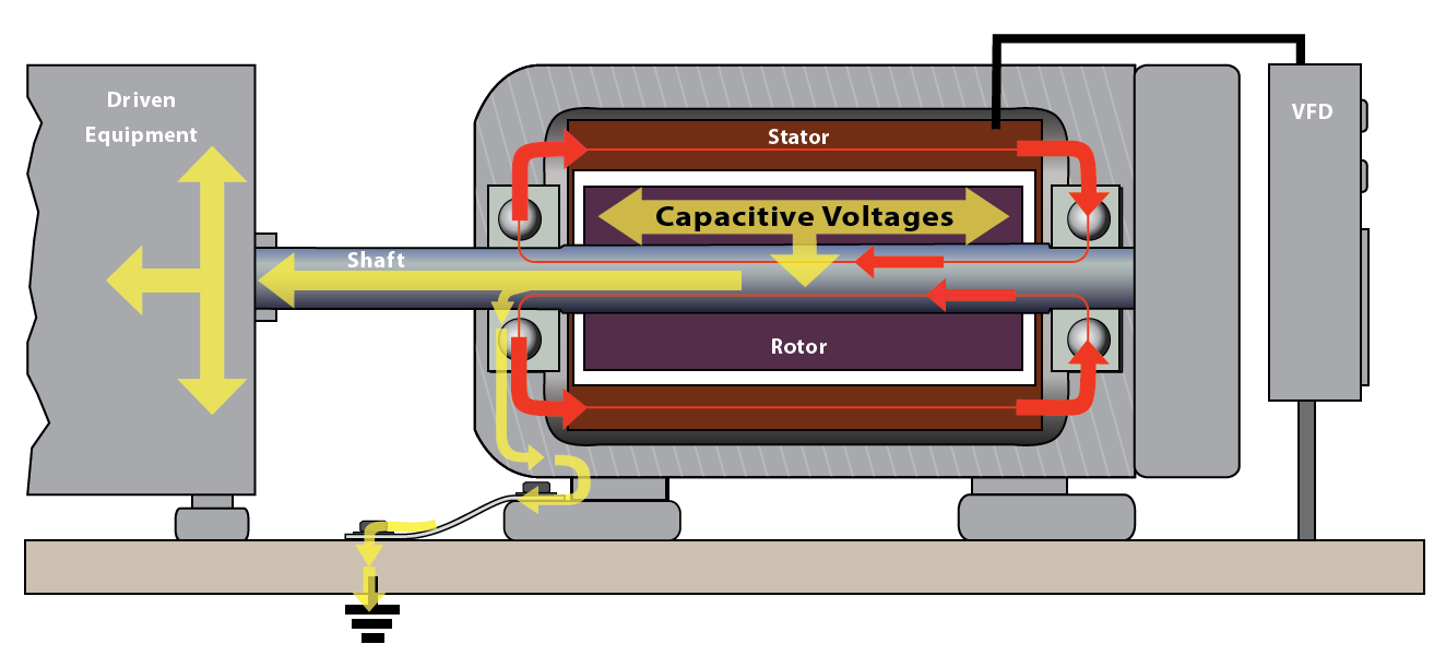
Source[1]
In larger frame size motors, usually 500 frame and larger, these voltages may be present under sinusoidal operation and are caused by magnetic dissymmetries in the construction of these motors. This results in the generation of a shaft end-to-end voltage. The current path, in this case, is from the motor frame through a bearing to the motor shaft, down the shaft, and through the other bearing back to the motor frame. This type of current can be interrupted by insulating one of the bearings, usually, the non-drive end bearing. If the shaft voltage is larger than 300 millivolts peak during testing[3], bearing insulation should be utilized.
Source[1]
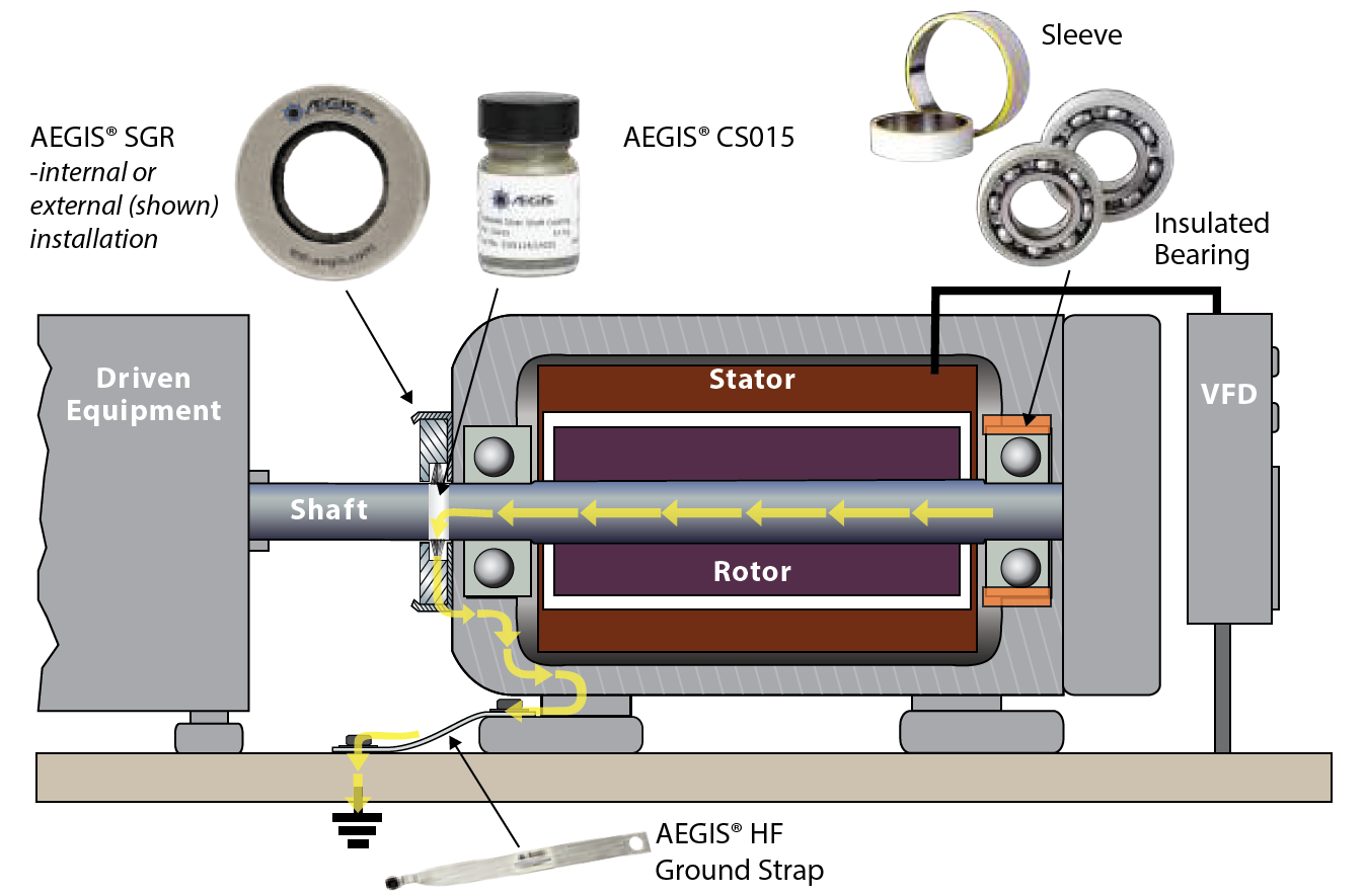
III. Common Mode Voltages: Mitigation
The current path could be through either or both bearings to the ground. Interruption of this current therefore requires insulating both bearings. Alternatively, shaft grounding brushes may be used to divert the current around the bearing. It should be noted that insulating the motor bearings will not prevent damage to other shaft-connected equipment.
Source[1]
Currently, there has been no conclusive study that has served to quantify the relationship of peak voltage from inverter operation to bearing life or failure. There is still no standard method for measuring this voltage. Because of this, the potential for problems cannot consistently be determined in advance of motor installation.
References: