Introduction
The standard IEC 60364 have used the following nomenclature to specify types of earthing:
- First letter – Relationship of the power system to earth:
- T = direct connection of one point to earth;
- I = all live parts isolated from earth, or one point connected to earth through a high impedance.
- Second letter – Relationship of the exposed-conductive-parts of the installation to earth:
- T = direct electrical connection of exposed-conductive-parts to earth, independently of the earthing of any point of the power system;
- N = direct electrical connection of the exposed-conductive-parts to the earthed point of the power system (in a.c. systems, the earthed point of the power system is normally the neutral point or, if a neutral point is not available, a line conductor).
From the above, there are three (3) main types of system earthings
- TN - Exposed-conductive parts connected to neutral
- TT - Earthed neutral
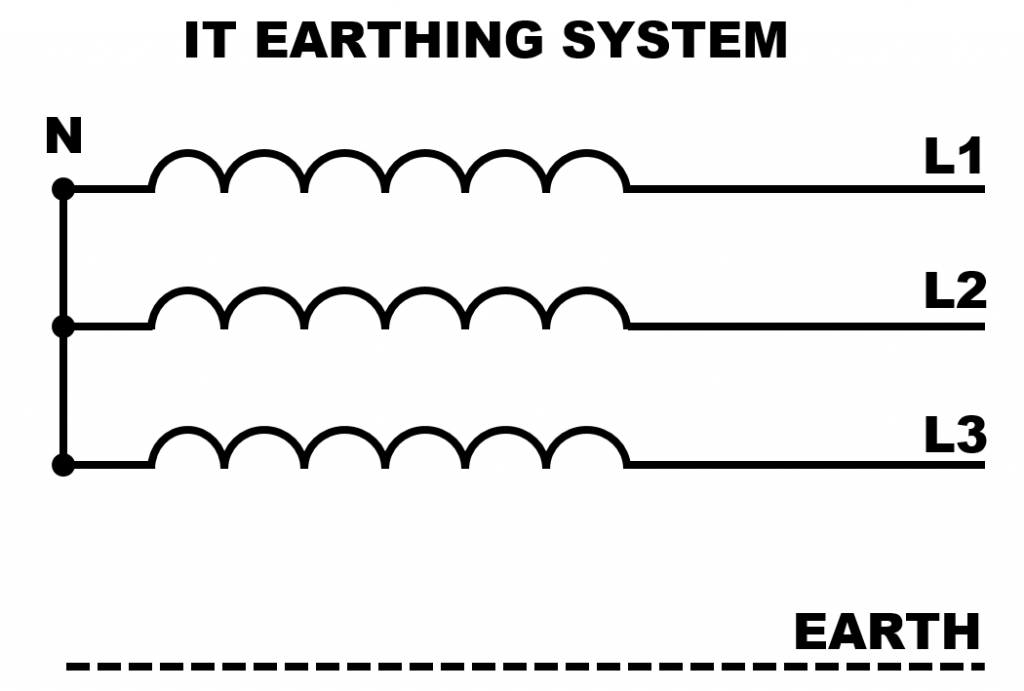
- IT - Unearthed (or impedance-earthed) neutral
The purpose of these three earthings is identical as regards protection of persons and property. They are considered to be equivalent with respect to safety of persons against indirect contacts. However, the same is not necessarily true for dependability of the Low Voltage electrical installation with respect to:
- Electrical power availability
- Installation maintenance
A thorough discussion of the types of earthing system is presented in the Cahier technique no. 172 - System earthings in LV
IT earthing system
Dr. Dirk Pieler, former CEO of Bender GmbH & Co. KG, Grünberg discussed the advantages and disadvantages of the IT earthing system in a Bender published technical paper. This technical paper deals with the reasons why IT earthing systems are to be used in power supply design and installations. Dr. Dirk Pieler provided 14 advantages and 2 disadvantages.
Insulation monitoring devices (IMDs)
IEC 61557-8 defines Insulation Monitoring Device(IMD) as device which permanently monitors the insulation resistance to earth of unearthed a.c. IT systems, a.c. IT systems with galvanically connected d.c. circuits having nominal voltages up to 1 000 V a.c., as well as monitoring the insulation resistance of unearthed d.c. IT systems with voltages up to 1 500 V d.c., independent from the method of measuring.
Insulation monitoring devices shall be capable of monitoring the insulation resistance RF of IT systems including symmetrical and asymmetrical allocation of the insulation resistance RF and to give an insulation warning if the insulation resistance RF between the system and earth falls below the response value Ra. This device shall not be provided with means for switching off the insulation monitoring function. IMDs is not protective device but it is part of the protective measure in IT systems. IMDs function as permanent monitoring of the insulation resistance of the unearthed IT system in any part of the system can be seen as safety functions which are part of the protective measures in an IT system.
Insulation fault location system (IFLs)
The IT system has many advantages over earthed systems and is suitable not only for the high requirements in operating theatres or in nuclear power stations, but practically everywhere. In many cases these days this system is not considered at all, even though it would be the better choice. The latest generation of insulation monitoring devices also offers many economical and technical advantages that benefit the operator. Sometimes the costs for an insulation monitoring device are cited as an argument against an IT system, but the opposite is the case: given the advantages listed above and and the economic impact they have, use in the commercial sector is always worthwhile!
Recommendations
Where the criticality of the continuity of an electrical supply system is the main factor in the selection of pwoer system earthing system, IT earthing system should be given the utmost consideration.