Important Note: Open circuit faults are presented in this article.
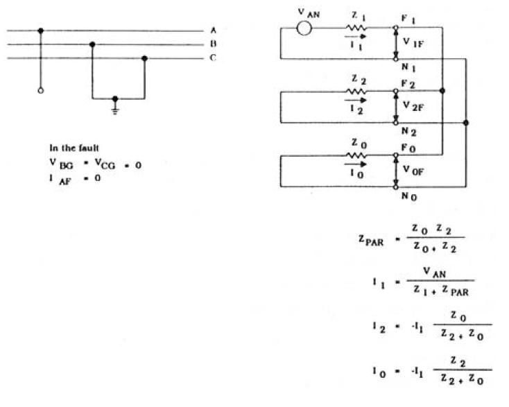
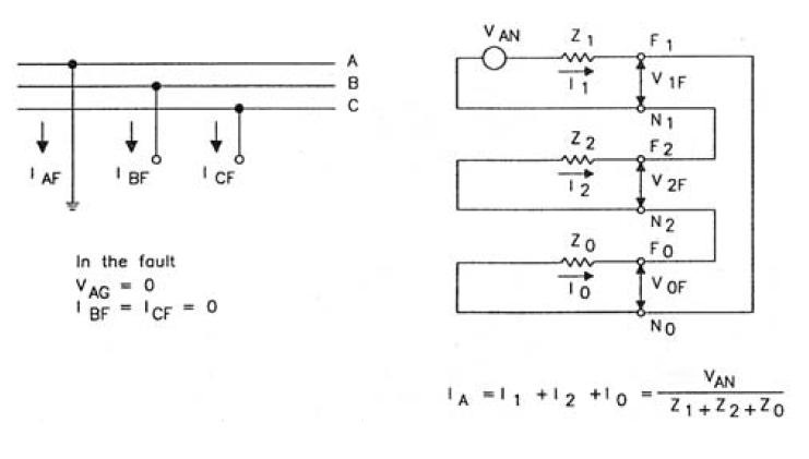
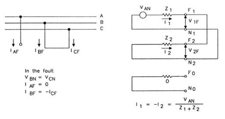
Calculating three-phase faults is very straightforward. Unbalance faults, however, have a little bit of challenge in it as it requires some imagination to be understood. To provide a better understanding of these types of faults, sequence network connection diagrams play a very vital role.
This question may be raised, "I could always use - Symmetrical components to solve my unbalance faults". You are right, that is the way to do it, but without knowing sequence network connection diagrams even with the values of symmetrical components, you will be facing a blank wall.
What is a sequence network connection diagram anyway? In a simple definition, a sequence network diagram is a simplified diagram where the positive, negative, and zero sequence components of a network or circuit are drawn separately and then connected depending on the type of fault in which the system have experienced. Still not quite clear? Yes, I know that is why a diagram will explain it best.
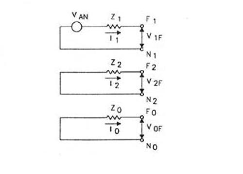
where:
VAN = phase to ground voltage
V1F = positive sequence terminal voltage
V2F = negative sequence terminal voltage
V0F = zero sequence terminal voltage
Z1 = positive sequence impedance
Z2 = negative sequence impedance
Z0 = zero sequence impedance
I1 = positive sequence current
I2 = negative sequence current
I0 = zero sequence current
F1, N1 = positive sequence terminals
F2, N2 = positive sequence terminals
F0, N0 = positive sequence terminals
Sequence network connection depending on the fault are the following:
1. Three phase fault
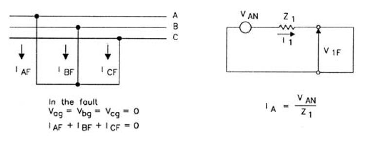
Note: A three-phase fault is a balance fault thus no zero-sequence component.
2. Line-to-ground fault
3. Phase-to-phase fault
4. Phase-to-phase-to-ground fault
