Introduction
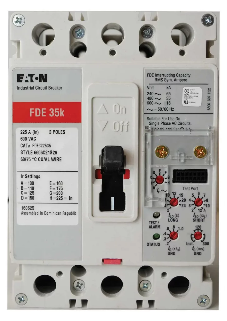
Molded Case Circuit Breakers (MCCBs) are used as protection devices to ensure safe operation of electrical circuits against overload, short circuit, and ground faults. MCCBs are used in residential applications, commercial and industrial installations; these breakers are used as a feeder breaker or branch circuit breaker.

Circuit breaker is defined as "devices designed to open or close a circuit by nonautomatic means, and to open the circuit automatically on a predetermined overcurrent without damage to itself when properly applied within its rating". The term "molded case" refers to the construction of the circuit breaker and the fact that the circuit breaker is an assembled unit in a supporting housing of an insulating material.
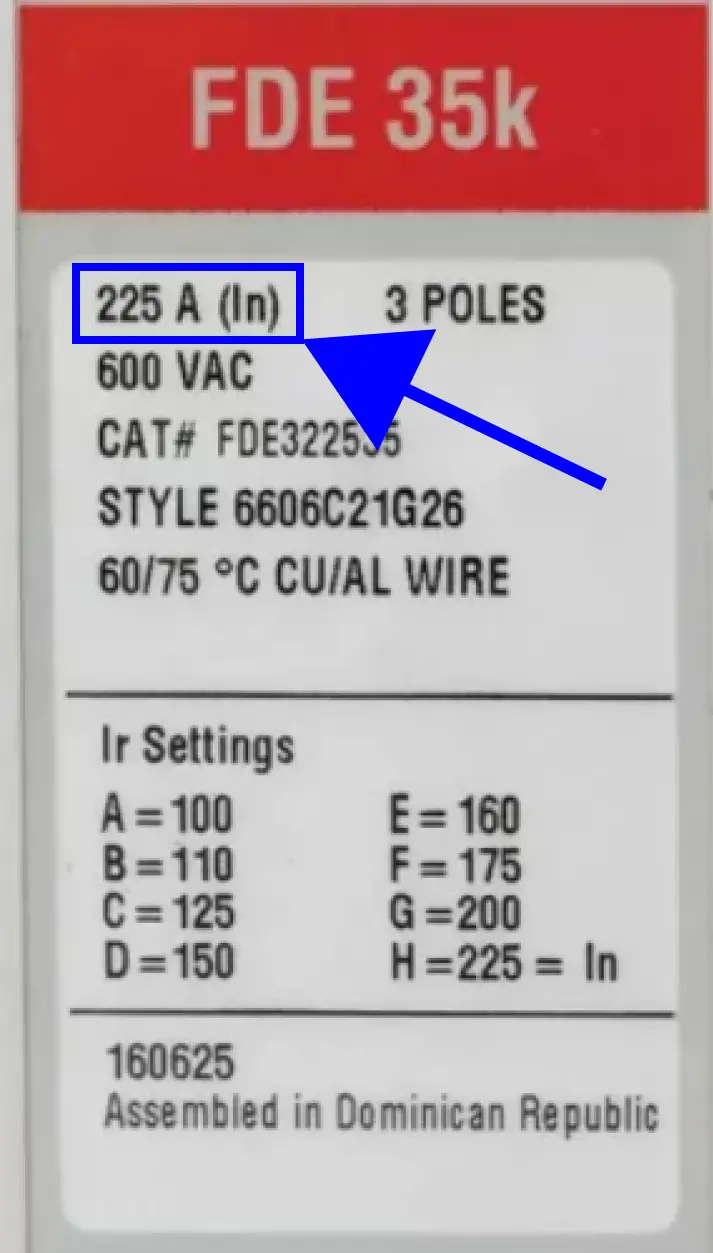
In addition, a MCCB is a circuit breaker which is assembled as an integral unit in a supportive and enclosed housing of Rated Current (In), [see Figure 1] – the marked current rating and the maximum RMS current a circuit breaker can carry continuously without tripping and the maximum current the circuit breaker will carry without changing, deleting, or adding a part or parts such as trip units and rating plugs.
MCCBs in the market have many configurations, voltage ranges, and current ranges to meet your project requirements. In most electrical systems, the MCCBs are rated for operation at 80% of their rated current. However, certain application use MCCBs rated for 100% operation.
This article defines certain terms applicable to circuit breakers, explains the ratings for 100% versus 80% operation, and provides cases where 100% rated MCCBs could be beneficial.
Essentially, circuit breakers are used as safety measure to protect electrical devices by combining multiple functional components, and can be used without damage when they are properly applied within their predetermined rating. MCCBs are available up to 3000 A rating.
MCCB Applications
Most circuit breakers used are 80% rated, which means that they can only be used continuously at 80% of their thermal current rating.
To get a clear definition on the rating, we can refer to the Philippine Electrical Code, PEC, Article 2.15.1.3 Overcurrent Protection, which states: “Where a feeder supplies continuous loads or any combination of continuous and noncontinuous loads, the rating of the overcurrent device shall not be less than the noncontinuous load plus 125% of the continuous load.
Exception: Where the assembly that includes the overcurrent devices protecting the feeder(s) are listed for operation at 100% of their rating, neither the ampere rating of the overcurrent device nor the ampacity of the feeder conductors shall be less than the sum of the continuous load plus the noncontinuous load.
The NEC defines a load as continuous when it is expected to run at maximum current for 3 hours or more. The rating of the conductors is important, because a load that is continuously running adds more heat to the wires than an intermittent load. Additional heat that is not accounted for can damage the conductors and other components of the system.
Examples
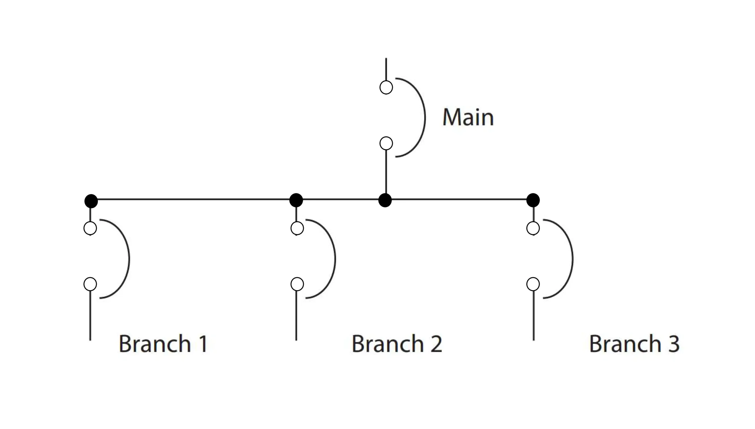
Using the Typical SLD in Figure 2, the following examples illustrate scenarios that compare 80% and 100%-rated breakers in the same application.

Example 1
- Branch 1
- Continuous Load: 400A
- Non-Continuous Load: 250 A
- Branch 2
- Continuous Load: 760 A
- Non-Continuous Load: 0 A
- Branch 3
- Continuous Load: 400 A
- Non-Continuous Load: 0 A
| Description | 80% Rated Design (Non-continuous load + 125% of continuous load) |
100% Rated Design (Non-continuous load + continuous load) |
|||||||
|---|---|---|---|---|---|---|---|---|---|
| Branch 1 | Branch 2 | Branch 3 | Main | Branch 1 | Branch 2 | Branch 3 | Main | ||
| Load Type | Continuous Load | 400 A | 760 A | 400 A | - | 400 A | 760 A | 400 A | - |
| Non-Continuous Load | 250 A | - | - | 250 A | - | - | |||
| Total Load | Calculation | 400(1.25)+250 | 760(1.25) | 400(1.25) | 750+950+500 | 400 | 760 | 400 | 650+760+400 |
| Sum | 750 A | 950 A | 500 A | 2200 A | 650 A | 760 A | 400 A | 1810 A | |
| Minimum Trip | 750 A | 950 A | 500 A | 2200 A | 650 A | 760 A | 400 A | 1810 A | |
| Recommended MCCB | 800 A | 1200 A | 600 A | 2500 A | 800 A | 800 A | 400 A | 2000 A | |
Example 2
- Branch 1
- Continuous Load: 180A
- Non-Continuous Load: 200 A
- Branch 2
- Continuous Load: 880 A
- Non-Continuous Load: 250 A
- Branch 3
- Continuous Load: 800 A
- Non-Continuous Load: 0 A
| Description | 80% Rated Design (Non-continuous load + 125% of continuous load) |
100% Rated Design (Non-continuous load + continuous load) |
|||||||
|---|---|---|---|---|---|---|---|---|---|
| Branch 1 | Branch 2 | Branch 3 | Main | Branch 1 | Branch 2 | Branch 3 | Main | ||
| Load Type | Continuous Load | 180 A | 880 A | 800 A | - | 180 A | 880 A | 800 A | - |
| Non-Continuous Load | 200 A | 250 A | - | 200 A | 250 A | - | |||
| Total Load | Calculation | 180(1.25)+200 | 880(1.25)+250 | 800(1.25) | 425+1350+1000 | 180+200 | 880+250 | 800 | 380+1130+800 |
| Sum | 425 A | 1350 A | 1000 A | 2775 A | 380 A | 1130 A | 800 A | 2310 A | |
| Minimum Trip | 425 A | 1350 A | 1000 A | 2775 A | 380 A | 1130 A | 800 A | 2310 A | |
| Recommended MCCB | 600 A | 1600 A | 1200 A | 3000 A | 400 A | 1200 A | 800 A | 2500 A | |
Summary
When you perform a system analysis done from branch to main feed, the results can provide a guide to whether your application is best suited for an 80% or 100%-rated MCCB that conforms to guidelines set out in PEC Article 2.15.1.3 Overcurrent Protection. It is also important that you understand the exception to PEC Article 2.15.1.3 concerning the rules about applying 100%-rated MCCBs to an entire system. The entire system, including the conductors, must be listed for 100% operation.
