Power:Transformer Inrush Current
Transformer Inrush Current
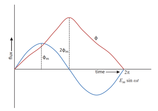
When a transformer works normally, the flux produced in the core is orthogonal to the applied voltage. When the voltage is zero, the flux waveform is at its negative peak. When a transformer is switched on from the primary by keeping the secondary open circulated, it acts as a simple inductance and the flux will start from zero as shown in Figure 1.
If the switching on is at the instant of voltage zero, the flux is initiated from the same origin of the voltage. The flux is the integral of the voltage, and the value of flux at time π can be written as
The excessive demand of flux would saturate the core and result in a sharp increase of the magne- tizing current. This increased current is termed as inrush current, and its magnitude can become several times of the full load current.
When the transformer is switched off, magnetizing current will follow a hysteresis loop and some residual flux may be retained in the core. If the residual flux, , is in the direction of the flux build-up, the peak flux would become , resulting in much higher inrush current. The waveform of the inrush current is a half-cycle sinusoidal wave superimposed by a DC component.
Problems with Transformer Inrush Current
- Mechanical Stresses
- The amplitude of the first peak of the inrush current can reach high value, and the consequent mechanical forces on the winding can cause excessive stresses on the windings. If there is fre- quent switching on of the transformer, the recurring surges can cause mechanical weakness of the winding.
- Over-voltage due to Harmonic Resonance
- The inrush current has very high harmonic content where the even harmonics are predominant. When any of the harmonics is close to the natural frequency of the system, there is a possibility of harmful resonant overvoltage.
- A power system can experience harmonic resonance in some of the following situations:
- - A black start of a system to a remote transformer
- - Energization of HV converter transformers
- - Energization of off-shore wind farms
- Nuisance Tripping of Transformer
- When the transformer is energized, the inrush current flows through one winding only and there is no balancing equivalent current on the energized winding. Even if second harmonic restraint is avail- able on the differential relay, extreme core saturation can cause tripping of a healthy transformer.
- Temporary Voltage Dip
- The inrush current may cause temporary voltage dips in connected system, which can take few cycles to return back to normalcy.
- Symphatetic Inrush
- When a transformer is switched on to the system, another transformer connected to the system can experience unexpected saturation and “sympathetic” inrush.
Effect of System and Switching Parameters on Inrush Current
- Source Resistance
- Increase of the source resistance will decrease the amplitude of inrush current, and it also causes faster decay of the amplitude of inrush current. When the system fault level at the transformer primary side is high, the source impedance and therefore the source resistance are low. Such a transformer will have higher magnitudes of inrush current lasting much longer than a transformer installed where the fault level is low.
- Switching Angle
- The higher amplitude of inrush current is at 0°. Increasing the switching angle will decrease the amplitude of inrush current. Also, increasing of the switching angle decreases the percentage sec- ond harmonic content of the inrush current. Though the highest amplitude of the inrush current is in the first cycle, the highest percentage second harmonic does not necessarily appear in the first cycle.
- Effect of Remnant Flux on the First Cycle Peak Current
- When the remnant flux changes, the first peak changes considerably. Switching at the zero residual flux and 90° switching angle necessarily need not reduce the magnitude of the inrush current. The optimum angle will have to be selected, based on the remnant flux direction and magnitude.
References
Power and Distribution Transformers - Practical Design Guide
© 2021 K.R.M. Nair
CRC Press


