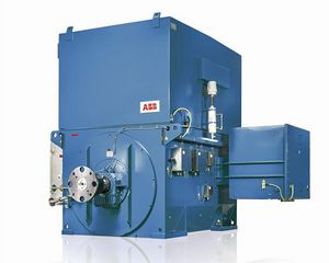
Induction Motors
Principles of Operation of Three Phase Motors
Induction motors[1] used in industrial drives consist of two main components: the stator and the rotor. The stator houses a three-phase winding that is powered by an external supply. The rotor features a set of single-bar conductors arranged in slots located just below its surface. These slots have narrow openings at the surface to secure the conductor bars in place. Each bar is connected at both ends to short-circuiting rings, forming a complete circuit. The stator winding is similar to that used in three-phase generators and synchronous motors.
The three-phase stator winding generates a rotating magnetic field with constant magnitude. The rotational speed of this field is determined by the supply frequency and the number of poles in the motor, with higher pole counts leading to slower rotation speeds. When the motor is first energized, the rotor remains stationary. The magnetic flux produced by the stator passes through the rotor, cutting across the rotor conductors as it rotates. Due to the sinusoidal spatial distribution of the flux, this rotation induces sinusoidal electromotive forces (emfs) in the rotor conductors. These emfs cause currents to flow in the rotor, resulting from transformer action—hence the term "induction motor."
With currents flowing in both the stator and rotor, the rotor conductors produce local magnetic fluxes. These fluxes interact with the stator's excitation flux, generating a torque on the rotor. If this torque surpasses the load torque, the rotor begins to rotate, accelerating until the torques balance. The rotor's rotation follows the direction of the stator's magnetic field, as the stator flux drives the rotor conductors.
At first, the rotor's speed is significantly lower than the stator field's speed, though it gradually increases. As the rotor accelerates, the rate at which the stator flux cuts the rotor conductors decreases. Consequently, the frequency and magnitude of the induced emfs in the rotor diminish. The local flux generated by the rotor conductors rotates more slowly relative to the rotor's surface. However, since the rotor body itself is in motion, the combined effect of its speed and the local rotor flux's rotational speed results in the rotor flux matching the stator field's speed.
The rotor current is limited by the short-circuit impedance of the rotor circuit, which includes resistance and inductive reactance. The inductive reactance is directly proportional to the frequency of the induced emfs in the rotor. As the rotor accelerates, two key effects occur:
- a) The rotor impedance increases.
- b) The rotor emf reduces.
These effects result in the supply current is being nearly constant during most of the run-up period.
The rotor speed can never reach the synchronous speed of the stator field. If it did, there would be no relative motion between the stator's magnetic field and the rotor conductors, resulting in no induced electromotive forces (emfs) or currents in the rotor. Without these currents, no torque would be produced to sustain motion.
As the rotor speed approaches synchronous speed, the relative motion between the stator field and the rotor diminishes, causing the induced emfs and currents in the rotor to decrease significantly. Consequently, the torque generated by the motor also drops rapidly. This continues until the torque developed by the motor equals the combined torque demand of the mechanical load, rotational friction, and windage losses. Once this equilibrium is reached, the motor operates at a steady speed just below synchronous speed.
Essential Characteristics
The key design characteristics that are most relevant to power system engineers include:
- Torque versus speed.
- Stator current versus speed.
While factors such as efficiency and power factor at operating conditions were historically secondary, the growing focus on energy conservation has increased the emphasis on efficiency. When selecting a motor, the primary objectives are:
- To provide sufficient torque throughout the entire acceleration period.
- To allow for easy starting using simple switching techniques.
- To be a standard design offered by the manufacturer.
Motor Torque versus Speed Characteristic
References
- ↑ Handbook of Electrical Engineering: For Practitioners in the Oil, Gas and Petrochemical Industry. Alan L. Sheldrake ©2003 John Wiley & Sons, Ltd ISBN: 0-471-49631-6
