Basics:Transformer Theory
Transformer Theory
Transformer is an essential device in electrical AC power distribution system, which is used to transform AC voltage magnitudes of any value obtained from a source to any desired value for the purpose of distribution and/or consumption. The development of power transformer dates back to 19th century. The main feature of a transformer is its constant VA rating whether referred to its primary side or the secondary side. With VA being constant (V refers to the voltage magnitude and A refers to the current magnitude in a transformer winding), it is possible to get a higher V with lower A or a lower V with a higher A, by choosing suitable ratio for the transformer.
The major benefit of such a device is its ability to take in the high current produced at relatively low voltage from the electrical generators and transform this power at a higher voltage level with lower current. This ensures that the power generated in the order of several megavolt amperes (MVA) is being transmitted at low current magnitudes in a cable of practical dimensions over very long distances. Today’s transmission and distribution systems are heavily dependent upon this technology and transformers are used extensively throughout the world.
Standard Transformer
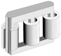
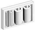
A standard transformer typically consists of a pair of windings, primary and secondary linked together by a magnetic core. The windings can be connected in any of the following types, which in turn decides to which category a transformer belongs. There are two basic types of the transformer viz., (a) shell type and (b) core type. These are illustrated in Figure .
In Figure 2, the windings are the concentric portions and the white solid portions refer to the metallic part of a transformer (laminations), which either surround the windings (shell type) or where the windings surround the core (core type). The windings are normally made of electrolytic grade copper and the metallic parts are made of steel (usually special steel called lamination steel). The metallic part linking the windings is referred to as the magnetic core of a transformer. In these transformers the source will be connected to just one winding only, which is termed as the primary winding. The voltage will be induced magnetically through the magnetic core linking the flux in the core with the other winding (called the secondary winding), since it derives its power from the primary winding.
Phasor Diagram
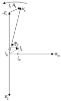
When an alternating current is applied to the primary winding, an alternating magneto motive force (mmf) is induced into the magnetic core and subsequently sets up an alternating flux passing through its body. This alternating flux in the core that links both the primary and secondary windings induces an electro motive force (emf) in both the windings. In the primary winding this emf is referred to as the back-emf and in an ideal situation, it would oppose the applied voltage to the primary windings such that there would be no flow of current (according to Lenz’s law). However the impedance in the windings causes a low current to pass in the primary winding and the current that flows in the primary winding is termed as the transformer magnetizing current. In the open secondary winding, this induced emf is referred to as the secondary open-circuit voltage, which basically refers to the voltage measured between the two ends of the winding. Figure 3 depicts the vectorial representation of the voltages, flux and currents that flow in a simple single phase transformer neglecting its impedances. The descriptions of the parameters are identified on the left hand side, which will give a clear idea on the phase angle differences between the voltages, currents and flux in a typical single phase transformer windings and its core.
Where:
Magnetic leakage is negligible and ignored.
References
Practical Power Distribution for Industry
Jan de Kock & Kobus Strauss
Copyright ©2004, IDC Technologies


