Uncategorized files
From Filipino Engineer Wiki
Showing below up to 76 results in range #1 to #76.
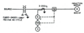 1-line Diagram.png 1,070 × 429; 173 KB
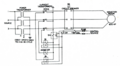 3-line Diagram.png 929 × 511; 272 KB
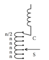 Bias Winding.png 516 × 631; 26 KB
 Cable waterfall.jpg 1,134 × 499; 110 KB
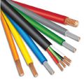 Cables.jpg 538 × 507; 58 KB
 Category A circuit-breaker.svg 316 × 290; 5 KB
 Category B circuit-breaker.svg 325 × 293; 7 KB
 Circuit Overload.jpg 800 × 400; 83 KB
 Circuit breaker with advanced electronic trip unit.svg 318 × 342; 7 KB
 Coarse-fine.png 513 × 605; 17 KB
 Compact NSX630N circuit breaker.svg 367 × 201; 57 KB
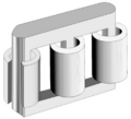 Core Type Transformer.png 717 × 652; 123 KB
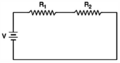 Electric Circuit.png 769 × 403; 32 KB
 Figure-2.10.3.3-Determination-of-Area-Behind-Sink-or-Range.png 800 × 1,031; 183 KB
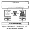 Figure-2.20.1.1-Branch-Circuit,-Feeder.png 800 × 784; 197 KB
 Figure-2.50.1.4-Grounding.png 1,979 × 3,038; 232 KB
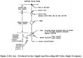 Figure 2.30.1.1(a) Overhead Service Supply.png 1,166 × 824; 394 KB
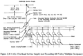 Figure 2.30.1.1(b) Overhead Service Supply.png 1,177 × 794; 296 KB
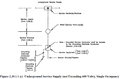 Figure 2.30.1.1(c) Underground Service Supply.png 1,197 × 785; 201 KB
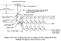 Figure 2.30.1.1(d) Underground Service Supply.png 1,114 × 739; 393 KB
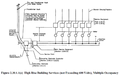 Figure 2.30.1.1(e) High Rise Building Services.png 1,223 × 763; 293 KB
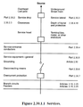 Figure 2.30.1.1 Services.png 676 × 872; 151 KB
 Figure 2.50.6.17.png 216 × 216; 14 KB
 Figure 3.10.1.60.png 2,717 × 3,470; 1.07 MB
 Five Limb Core Type Transformer.png 721 × 616; 136 KB
 Fotolia 1481286 M-798471.jpg 1,600 × 1,066; 46 KB
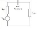
 Gen bus house load point.gif 225 × 174; 4 KB
 Graphic Scale Bars.jpg 1,024 × 723; 29 KB
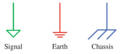 Grounding Symbols.png 810 × 365; 21 KB
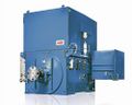 HV motor.jpg 500 × 400; 64 KB
 Harry King Corral Avenido - Filipino Engineer.jpg 125 × 125; 26 KB
 Highlights and Impacts.pdf 1,500 × 1,125, 181 pages; 7.79 MB
 IEC-60445 2010.png 663 × 1,024; 104 KB
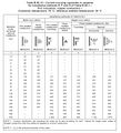 IEC 60364-552 TableB5210.jpg 778 × 853; 124 KB
 IEEE NESC C2 2014 Table 124-1.png 1,000 × 1,339; 85 KB
 Inf bus vf.gif 485 × 177; 4 KB
 Limit of Approach.png 794 × 617; 104 KB
 Linear.png 371 × 552; 14 KB
 Load Tap Changer.webp 554 × 450; 118 KB
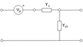
 MS Equiv Circuit.jpg 539 × 218; 12 KB
 MS Model.jpg 290 × 338; 8 KB
 MS Near Thevenin.jpg 262 × 202; 6 KB
 MS Near Thevenin1.jpg 262 × 202; 5 KB
 NFPA 5000-2015.png 760 × 1,192; 660 KB
 NFPA 70B-2019 cover.png 1,700 × 2,200; 30 KB
 Oil-field-e1454004632383.png 777 × 437; 355 KB
 PEC 2009.png 402 × 559; 361 KB
 PEC 2017.jpg 683 × 849; 59 KB
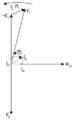 Phasor diagram - Single Phase Transformer.png 430 × 706; 35 KB
 Pipeline model 1.png 366 × 208; 5 KB
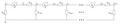 Pipeline model 2.png 1,020 × 208; 13 KB
 Power-Transformer.jpg 2,092 × 1,728; 440 KB
 Power-line-short-circuit.jpg 640 × 431; 61 KB
 Power-line.png 1,920 × 1,080; 744 KB
 Prospective and actual currents.svg 258 × 230; 39 KB
 Protection Relays.jpg 720 × 421; 48 KB
 Reactive Auto-transformer Switching.png 433 × 712; 22 KB
 Resistive Switching.png 436 × 737; 24 KB
 Reversing.png 547 × 567; 16 KB
 Shell Type Transformer.png 702 × 632; 123 KB
 Single-Line-Diagram.webp 348 × 819; 13 KB
 Single-line-diagram.gif 1,174 × 558; 20 KB
 Single Line Diagram.png 2,516 × 2,272; 107 KB
 Table-2.10.1.2-Specific-Purpose-Branch-Circuits.png 800 × 1,669; 1.09 MB
 Table-2.10.2.6-Summary-of-Branch-Circuit-Requirements.png 800 × 329; 116 KB
 Table-2.20.1.3-Additional-Load-Calculation-References.png 800 × 802; 341 KB
 Table-2.20.2.3-General-Lighting-Loads-by-Occupancy.png 2,664 × 3,522; 713 KB
 Table 2.20.3.3 Lighting Load Demand Factors.png 2,644 × 2,742; 687 KB
 Table 3.10.1.13 Conductor Application and Insulations.jpg 1,239 × 3,693; 1.44 MB
 Thermal-magnetic circuit breaker.svg 314 × 345; 6 KB
 Towerline.jpg 386 × 470; 23 KB
 Transformer Voltage and Flux.png 775 × 547; 37 KB
 Typical-Earthing-Grid-with-Rodsjpg.jpg 1,024 × 450; 32 KB
 Typical Single Line Diagram.jpg 3,785 × 3,657; 960 KB
 VSD.jpg 1,138 × 1,536; 226 KB
 Ver Pangonilo - Filipino Engineer.jpg 125 × 125; 6 KB


_Overhead_Service_Supply.png)
_Overhead_Service_Supply.png)
_Underground_Service_Supply.png)
_Underground_Service_Supply.png)
_High_Rise_Building_Services.png)


