Power:Transformer Load Tap Changers
Transformer Load Tap Changers
A tap changer is a mechanism in transformers which allows for variable turn ratios to be selected in distinct steps. This is done by connecting to a number of access points known as taps along either the primary or secondary winding.
I. Introduction
The flicker of the house lights in the evening when most people are at home and started using electricity for household chores is a sign of a load tap changer (LTC) tap change. The increase in electrical load on the distribution network causes the voltage to sag below its nominal value. This voltage sage triggers a signal to the LTC to change taps to adjust the voltage back to its nominal value with some tolerance.

There are many applications of transformers in modern electric power systems. The role of a transformer is to convert the electrical energy from one voltage level to another. As power systems become larger and more complex, power transformers play a major role in the efficiency and stability of the power the system. Each transformer installed in a network, there is an optimal voltage ratio for an optimal operation of the system. Unfortunately, this optimal voltage ratio varies depending on the operating conditions of the total network. Early electric power systems, it was evident that for the power systems to operate efficiently, transformer voltage ratios needed to be adjustable without interrupting the flow of energy. This is the role of an LTC.
II. General Description of LTC
An load tap changer (LTC) is a device that connects different taps of tapped windings of transformers without interrupting the load. It must be capable of switching from one tap position to another without at any time interrupting the flow of the current to the load and without at any time creating a short circuit between any two taps of the transformer winding. Tap changing transformers are used to control the voltage or the phase angle or both in a regulated circuit.
An LTC is made of four elements:
- A selector switch is used to select the active tap
- A changeover switch or reversing switch when it reverses the polarity of the tapped winding
- A transition mechanism including an arcing or diverter switch
- A driving mechanism, a motor and gear box and controls to drive the tap changer system
Two Types of Tap Changers
- 1. In-tank
- The cover-mounted, in-tank tap changer, known as the Jansen type, sits in the main transformer oil together with the core-and-coil assembly. Its selector and changeover switches are at the bottom of the tap changer in the main oil. The arcing (diverter) switch is located in a separate compartment at the top, usually within a sealed cylinder made of fiberglass or other similar material. All arcing is confined to this compartment. They exist in single-phase or three-phase neutral end Wye (Y)-connected versions. For three-phase fully insulated applications, three single-phase tap changers must be used. This type of tap changer is used for higher voltages or current levels.
- 2. Separate compartment
- The side-mounted, separate compartment types have their own box and are assembled separately from the transformer. They are bolted to the side of the tank and connected to the transformer tapped windings through a connecting board. Their selector, changeover, and arcing switches are located in an oil compartment completely isolated from the main transformer oil. Some of them have two compartments, one for the arcing switch and one for the selector and changeover switches. Others have everything in one compartment only. They are available in three-phase assembly, either Wye connected for application at the neutral end of a three-phase transformer or fully insulated for applications at the line end.
III. Types of Regulation
The main types of regulation are the following:
- 1. Linear (Figure 2)
- In linear switching, tapped turns are added in series with the main winding and their voltage adds to the voltage of the main winding. No changeover switch is needed for this type. The tapped winding is totally bypassed in the minimum voltage position. The rated position can be any one of the tap positions.
- 2. Reversing (Figure 3)
- In a reversing type of regulation, the whole tapped winding can be connected in additive or reversed polarity with respect to the main winding. The tapped turns can add or subtract their voltage with respect to the main winding. The tapped winding is totally bypassed in the neutral (midrange) voltage position. The rated position is normally the middle one. The total number of positions available is twice the number of sections in the tapped winding plus one.
- 3. Coarse–fine (Figure 4)
- The coarse–fine regulation can be defined as a two-stage linear regulation where the first or coarse stage contains a large number of turns, which can be totally bypassed, by the changeover selector. These turns are shown as a single loop in the top coil of the figure. Fine regulation is achieved with the selector switch. Normally, the coarse section contains as many turns as the tapped winding plus one section. In that way, the total number of positions available is twice the number of sections in the tapped winding plus one.
- 4. Bias winding (Figure 5)
- The bias winding type of regulation is similar to the coarse–fine except that the number of turns in the bias winding is half the turns of one section of the tapped winding. It is used to provide half steps between the main tap steps. Thus, the total number of positions available is twice the number of sections in the tapped winding plus one. The bias winding technique can be combined with the reversing scheme to provide twice the number of positions (four times the number of sections in the tapped winding plus one) at the expense of adding one more switch and increasing the complexity of the switching and driving mechanism.
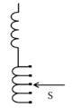
Figure 2 - Linear Tap Changer
(S - Selector Switch)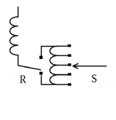
Figure 3 - Reversing Tap Changer
(R - Reversing Switch)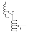
Figure 4 - Course-Fine Tap Changer
(C - Changeover Switch)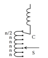
Figure 5 - Bias Winding Tap Changer


