Power:Transformers
CONSTRUCTION, TYPES, AND CHARACTERISTICS
A transformer is an apparatus for converting electrical power in an ac system at one voltage or current into electrical power at some other voltage or current without the use of rotating parts.
A transformer consists essentially of three parts:
- the primary coil which carries the alternating current from the supply lines,
- the core of mag- netic material in which is produced an alternating magnetic flux, and the
- secondary coil in which is generated an emf by the change of magnetism in the core which it surrounds.
Sometimes the transformer may have only one winding, which will serve the dual purpose of primary and secondary coils.
The high-tension winding is composed of many turns of relatively fine copper wire, well insulated to withstand the voltage impressed on it. The low-tension winding is com- posed of relatively few turns of heavy copper wire capable of carrying considerable current at a low voltage.
Transformer terminology
- Primary Winding
- the winding of the trans- former which is connected to the source of power. It may be either the high- or the low- voltage winding, depending upon the application of the transformer.
- Secondary Winding
- the winding of the transformer which delivers power to the load. It may be either the high- or the low-voltage winding, depending upon the application of the transformer.
- Core
- The magnetic circuit upon which the windings are wound.
- High-tension (high voltage) winding
- The winding which is rated for the higher voltage.
- Low-tension (low voltage) winding
- The winding which is rated for the lower voltage.
- Step-up transformer
- A transformer which is connected that the output voltage is greater than the supplied voltage.
- Step-down transformer
- A transformer which is connected that the output voltage is less than that supplied.
The actual transformer may be the same in one case as in the other, the terms step-up and step-down relating merely to the application of the apparatus.
Transformer Cores
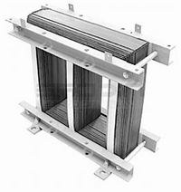
The traditional transformer cores were made up of stacks of sheet-steel punchings firmly clamped together. The laminations are coated with a thin varnish to reduce eddy-current losses. When the laminations are not coated with varnish, a sheet of insulating paper is inserted between laminations at regular intervals.
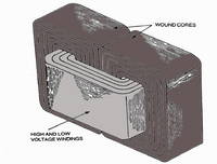
A new type of core construction consists of a continuous strip of silicon steel which is wound in a tight spiral around the insulated coils and firmly held by spot welding at the end. This type of construction reduces the cost of manufacture and reduces the power loss in the core due to eddy currents.
Classification of transformers
1. According to method of cooling
- a. Self-air–cooled (dry type)
- b. Air-blast–cooled (dry type)
- c. Liquid-immersed, self-cooled
- d. Oil-immersed, combination self-cooled and air-blast
- e. Oil-immersed, water-cooled
- f. Oil-immersed, forced-oil–cooled
- g. Oil-immersed, combination self-cooled and water-cooled
2. According to insulation between windings
- a. Windings insulated from each other
- b. Autotransformers
3. According to number of phases
- a. Single-phase
- b. Polyphase
4. According to method of mounting
- a. Pole and platform
- b. Subway
- c. Vault
- d. Special
5. According to purpose
- a. Constant-voltage
- b. Variable-voltage
- c. Current
- d. Constant-current
6. According to service
- a. Large power
- b. Distribution
- c. Small power
- d. Sign lighting
- e. Control and signaling

