Basics:Circuit Breaker Characteristics: Difference between revisions
No edit summary |
|||
| (14 intermediate revisions by the same user not shown) | |||
| Line 1: | Line 1: | ||
={{SUBPAGENAME}}= | |||
__TOC__ | __TOC__ | ||
| Line 13: | Line 14: | ||
This is the voltage at which the circuit-breaker has been designed to operate, in normal (undisturbed) conditions. | This is the voltage at which the circuit-breaker has been designed to operate, in normal (undisturbed) conditions. | ||
Other values of voltage are also assigned to the circuit-breaker, corresponding to disturbed conditions as noted in [[ | Other values of voltage are also assigned to the circuit-breaker, corresponding to disturbed conditions as noted in [[Basics:Circuit_Breaker_Characteristics#Rated_insulation_voltage_(Ui) | other characteristics of a circuit-breaker]]. | ||
== Rated current (In) == | == Rated current (In) == | ||
| Line 25: | Line 26: | ||
Derating a circuit-breaker is achieved therefore, by reducing the trip-current setting of its overload relay, and marking the CB accordingly. The use of an electronic-type of tripping unit, designed to withstand high temperatures, allows circuit-breakers (derated as described) to operate at 60°C (or even at 70°C) ambient. | Derating a circuit-breaker is achieved therefore, by reducing the trip-current setting of its overload relay, and marking the CB accordingly. The use of an electronic-type of tripping unit, designed to withstand high temperatures, allows circuit-breakers (derated as described) to operate at 60°C (or even at 70°C) ambient. | ||
'''Note:''' In for circuit-breakers (in IEC 60947-2) is equal to Iu for switchgear generally, Iu being the rated uninterrupted current. | '''Note:''' In for circuit-breakers (in IEC 60947-2) is equal to Iu for switchgear generally, Iu being the rated uninterrupted current. | ||
== Frame-size rating == | == Frame-size rating == | ||
| Line 42: | Line 43: | ||
=== Example === | === Example === | ||
[[File:Compact_NSX630N_circuit_breaker.svg|thumb|Figure 1 - Example of a Compact NSX630N circuit breaker with a Micrologic rated 400A adjusted to 0.9 to give Ir = 360 A]] | |||
A NSX630N circuit-breaker equipped with a 400 A Micrologic 6.3E overcurrent trip relay, set at 0.9, will have a trip-current setting: | A NSX630N circuit-breaker equipped with a 400 A Micrologic 6.3E overcurrent trip relay, set at 0.9, will have a trip-current setting: | ||
| Line 50: | Line 51: | ||
'''Note:''' For circuit-breakers equipped with non-adjustable overcurrent-trip relays, Ir = In. Example: for iC60N 20 A circuit-breaker, | '''Note:''' For circuit-breakers equipped with non-adjustable overcurrent-trip relays, Ir = In. Example: for iC60N 20 A circuit-breaker, | ||
Ir = In = 20 A. | Ir = In = 20 A. | ||
== Short-circuit relay trip-current setting (Im) == | == Short-circuit relay trip-current setting (Im) == | ||
| Line 61: | Line 60: | ||
*Indicated by the manufacturer for industrial type CBs according to related standards, notably IEC 60947-2. | *Indicated by the manufacturer for industrial type CBs according to related standards, notably IEC 60947-2. | ||
For the latter circuit-breakers there exists a wide variety of tripping devices which allow a user to adapt the protective performance of the circuit-breaker to the particular requirements of a load ( | For the latter circuit-breakers there exists a wide variety of tripping devices which allow a user to adapt the protective performance of the circuit-breaker to the particular requirements of a load (Figure 1, Figure 2, Figure 3). | ||
{{tb-start|id=Tab1267|num=H28|title=Tripping-current ranges of overload and short-circuit protective devices for LV circuit breakers|cols=5}} | {{tb-start|id=Tab1267|num=H28|title=Tripping-current ranges of overload and short-circuit protective devices for LV circuit breakers|cols=5}} | ||
| Line 106: | Line 105: | ||
|B= For industrial use, IEC standards do not specify values. The above values are given only as being those in common use.}} | |B= For industrial use, IEC standards do not specify values. The above values are given only as being those in common use.}} | ||
[[File:Thermal-magnetic_circuit_breaker.svg|thumb|Figure 2 Tripping curve of a thermal-magnetic circuit breaker]] | |||
[[File:Circuit_breaker_with_advanced_electronic_trip_unit.svg|thumb|Figure 3 - Tripping curve of a circuit breaker with advanced electronic trip unit<br> | |||
'''Ir''': Overload (thermal or long-delay) relay trip-current setting<br> | '''Ir''': Overload (thermal or long-delay) relay trip-current setting<br> | ||
'''Im''': Short-circuit (magnetic or short-delay) relay trip-current setting<br> | '''Im''': Short-circuit (magnetic or short-delay) relay trip-current setting<br> | ||
'''Ii''': Short-circuit instantaneous relay trip-current setting.<br> | '''Ii''': Short-circuit instantaneous relay trip-current setting.<br> | ||
'''Icu''': Breaking capacity | '''Icu''': Breaking capacity ]] | ||
== Circuit breaker suitable for isolation == | == Circuit breaker suitable for isolation == | ||
| Line 183: | Line 182: | ||
* '''Selectivity category B''' comprises circuit breakers providing selectivity by having a short-time withstand current rating and an associated short-time delay. For this category of circuit breaker, manufacturer shall provide the value of short-circuit current (Icw) that can be withstood for a specified time. | * '''Selectivity category B''' comprises circuit breakers providing selectivity by having a short-time withstand current rating and an associated short-time delay. For this category of circuit breaker, manufacturer shall provide the value of short-circuit current (Icw) that can be withstood for a specified time. | ||
It is possible to delay the tripping of this type circuit breaker, where the fault-current level is lower than this short-time withstand current rating (Icw) (see | It is possible to delay the tripping of this type circuit breaker, where the fault-current level is lower than this short-time withstand current rating (Icw) (see Figure 4). | ||
This is generally applied to power open type or “Air” circuit breakers and to certain heavy-duty molded-case types. Icw is the maximum current that the B category circuit breaker can withstand, thermally and electrodynamically, without sustaining damage, for a period of time given by the manufacturer. | This is generally applied to power open type or “Air” circuit breakers and to certain heavy-duty molded-case types. Icw is the maximum current that the B category circuit breaker can withstand, thermally and electrodynamically, without sustaining damage, for a period of time given by the manufacturer. | ||
[[File:Category_B_circuit-breaker.svg|thumb|Figure 4 - Category B circuit-breaker]] | |||
* '''Selectivity category A''' comprises all other circuit breakers. This category of circuit breaker has no deliberate delay in the operation of the “instantaneous” short-circuit magnetic tripping device (see | * '''Selectivity category A''' comprises all other circuit breakers. This category of circuit breaker has no deliberate delay in the operation of the “instantaneous” short-circuit magnetic tripping device (see Figure 5). Usually molded-case type circuit breakers or modular circuit breaker are category A These circuit breakers may provide selectivity under short-circuit conditions by other means. But manufacturer will not provide Icw value. | ||
[[File:Category_A_circuit-breaker.svg|thumb|Figure 5 - Category A circuit-breaker]] | |||
== Rated making capacity (Icm) == | == Rated making capacity (Icm) == | ||
| Line 238: | Line 237: | ||
Many designs of LV circuit-breakers feature a short-circuit current limitation capability, whereby the current is reduced and prevented from reaching its (otherwise) maximum peak value (see {{FigureRef|H35}}). The current-limitation performance of these CBs is presented in the form of graphs, typified by that shown in {{FigureRef|H36}}, diagram (a)}} | Many designs of LV circuit-breakers feature a short-circuit current limitation capability, whereby the current is reduced and prevented from reaching its (otherwise) maximum peak value (see {{FigureRef|H35}}). The current-limitation performance of these CBs is presented in the form of graphs, typified by that shown in {{FigureRef|H36}}, diagram (a)}} | ||
The fault-current limitation capacity of a CB concerns its ability, more or less effective, in preventing the passage of the maximum prospective fault-current, permitting only a limited amount of current to flow, as shown in | The fault-current limitation capacity of a CB concerns its ability, more or less effective, in preventing the passage of the maximum prospective fault-current, permitting only a limited amount of current to flow, as shown in Figure 6. | ||
[[File:Prospective_and_actual_currents.svg|thumb||Figure 6 - Prospective and actual currents]] | |||
The current-limitation performance is given by the CB manufacturer in the form of curves (see {{FigRef|H36}}). | The current-limitation performance is given by the CB manufacturer in the form of curves (see {{FigRef|H36}}). | ||
| Line 282: | Line 281: | ||
Selective protection schemes and cascading are compatible, in the Compact NSX range, up to the full short-circuit breaking capacity of the switchgear. | Selective protection schemes and cascading are compatible, in the Compact NSX range, up to the full short-circuit breaking capacity of the switchgear. | ||
== References == | |||
# [https://www.electrical-installation.org/enwiki/Fundamental_characteristics_of_a_circuit-breaker#cite_ref-Ref1_1-0 Fundamental characteristics of a circuit-breaker] | |||
# [https://www.electrical-installation.org/enwiki/Other_characteristics_of_a_circuit-breaker Other characteristics of a circuit-breaker] | |||
Latest revision as of 14:51, 10 April 2024
Basics:Circuit Breaker Characteristics
Fundamental Characteristics
The fundamental characteristics of a circuit-breaker are:
- Its rated voltage Ue
- Its rated current In
- Its tripping-current-level adjustment ranges for overload protection (Ir or Irth) and for short-circuit protection (Im)
- Its short-circuit current breaking rating (Icu for industrial CBs; Icn for domestic-type CBs).
Rated operational voltage (Ue)
This is the voltage at which the circuit-breaker has been designed to operate, in normal (undisturbed) conditions.
Other values of voltage are also assigned to the circuit-breaker, corresponding to disturbed conditions as noted in other characteristics of a circuit-breaker.
Rated current (In)
This is the maximum value of current that a circuit-breaker, fitted with a specified overcurrent tripping relay, can carry indefinitely at an ambient temperature stated by the manufacturer, without exceeding the specified temperature limits of the current carrying parts.
Example
A circuit-breaker rated at In = 125 A for an ambient temperature of 40°C will be equipped with a suitably calibrated overcurrent tripping relay (set at 125 A). The same circuit-breaker can be used at higher values of ambient temperature however, if suitably “derated”. Thus, the circuit-breaker in an ambient temperature of 50°C could carry only 117 A indefinitely, or again, only 109 A at 60°C, while complying with the specified temperature limit.
Derating a circuit-breaker is achieved therefore, by reducing the trip-current setting of its overload relay, and marking the CB accordingly. The use of an electronic-type of tripping unit, designed to withstand high temperatures, allows circuit-breakers (derated as described) to operate at 60°C (or even at 70°C) ambient.
Note: In for circuit-breakers (in IEC 60947-2) is equal to Iu for switchgear generally, Iu being the rated uninterrupted current.
Frame-size rating
A circuit breaker which can be fitted with overcurrent tripping units of different current level-setting ranges, is assigned a rating which corresponds to the highest current-level-setting tripping unit that can be fitted.
Example
A Compact NSX630N circuit-breaker can be equipped with 11 electronic trip units from 150 A to 630 A. The size of the circuit-breaker is 630A.
Overload relay trip-current setting (Irth or Ir)
Apart from small circuit-breakers which are very easily replaced, industrial circuit-breakers are equipped with removable, i.e. exchangeable, overcurrent-trip relays. Moreover, in order to adapt a circuit-breaker to the requirements of the circuit it controls, and to avoid the need to install over-sized cables, the trip relays are generally adjustable. The trip-current setting Ir or Irth (both designations are in common use) is the current above which the circuit-breaker will trip. It also represents the maximum current that the circuit-breaker can carry without tripping. That value must be greater than the maximum load current IB, but less than the maximum current permitted in the circuit Iz (see chapter Sizing and protection of conductors ).
The thermal-trip relays are generally adjustable from 0.7 to 1.0 times In, but when electronic devices are used for this duty, the adjustment range is greater; typically 0.4 to 1 times In.
Example
A NSX630N circuit-breaker equipped with a 400 A Micrologic 6.3E overcurrent trip relay, set at 0.9, will have a trip-current setting:
Ir = 400 x 0.9 = 360 A
Note: For circuit-breakers equipped with non-adjustable overcurrent-trip relays, Ir = In. Example: for iC60N 20 A circuit-breaker,
Ir = In = 20 A.
Short-circuit relay trip-current setting (Im)
Short-circuit tripping relays (instantaneous or slightly time-delayed) are intended to trip the circuit-breaker rapidly on the occurrence of high values of fault current. Their tripping threshold Im is:
- Either fixed by standards for domestic type CBs, e.g. IEC 60898, or,
- Indicated by the manufacturer for industrial type CBs according to related standards, notably IEC 60947-2.
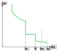
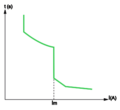
For the latter circuit-breakers there exists a wide variety of tripping devices which allow a user to adapt the protective performance of the circuit-breaker to the particular requirements of a load (Figure 1, Figure 2, Figure 3).
| Type of protective relay | Overload protection |
Short-circuit protection | |||
|---|---|---|---|---|---|
| Domestic breakers IEC 60898 | Thermal- magnetic | Ir = In | Low setting type B 3 In ≤ Im ≤ 5 In |
Standard setting type C 5 In ≤ Im ≤ 10 In |
High setting circuit type D 10 In ≤ Im ≤ 20 InTemplate:Tn |
| Modular industrial circuit-breakersTemplate:Tn | Thermal- magnetic | Ir = In fixed |
Low setting type B or Z 3.2 In ≤ fixed ≤ 4.8 In |
Standard setting type C 7 In ≤ fixed ≤ 10 In |
High setting type D or K 10 In ≤ fixed ≤ 14 In |
| Industrial circuit-breakersTemplate:Tn
IEC 60947-2 |
Thermal- magnetic | Ir = In fixed | Fixed: Im = 7 to 10 In | ||
| Adjustable: 0.7 In ≤ Ir ≤ In | |||||
Adjustable:
| |||||
| Electronic | Long delay 0.4 In ≤ Ir ≤ In |
Short-delay, adjustable 1.5 Ir ≤ Im ≤ 10 Ir Instantaneous (I) fixed | |||
Circuit breaker suitable for isolation
A circuit-breaker is suitable for isolating a circuit if it fulfills all the conditions prescribed for a disconnector (at its rated voltage) in the relevant standard. In such a case it is referred to as a circuit-breaker-disconnector and marked on its front face with the symbol
File:Circuit-breaker-symbol.svg
All Acti 9, Compact NSX and Masterpact LV switchgear of Schneider Electric ranges are in this category.
Rated short-circuit breaking capacity (Icu or Icn)
The short-circuit current-breaking rating of a CB is the highest (prospective) value of current that the CB is capable of breaking without being damaged. The value of current quoted in the standards is the rms value of the AC component of the fault current, i.e. the DC transient component (which is always present in the worst possible case of short-circuit) is assumed to be zero for calculating the standardized value. This rated value (Icu) for industrial CBs and (Icn) for domestic-type CBs is normally given in kA rms.
Icu (rated ultimate s.c. breaking capacity) and Ics (rated service s.c. breaking capacity) are defined in IEC 60947-2 together with a table relating Ics with Icu for different categories of utilization A (instantaneous tripping) and B (time-delayed tripping) as discussed in Other characteristics of a circuit-breaker .
Tests for proving the rated s.c. breaking capacities of CBs are governed by standards, and include:
- Operating sequences, comprising a succession of operations, i.e. closing and opening on short-circuit
- Current and voltage phase displacement. When the current is in phase with the supply voltage (cosφ for the circuit = 1), interruption of the current is easier than that at any other power factor. Breaking a current at low lagging values of cosφ is considerably more difficult to achieve; a zero power-factor circuit being (theoretically) the most onerous case.
In practice, all power-system short-circuit fault currents are (more or less) at lagging power factors, and standards are based on values commonly considered to be representative of the majority of power systems. In general, the greater the level of fault current (at a given voltage), the lower the power factor of the fault-current loop, for example, close to generators or large transformers.
Template:FigureRef below extracted from IEC 60947-2 relates standardized values of cos φ to industrial circuit-breakers according to their rated Icu.
- Following an open - time delay - close/open sequence to test the Icu capacity of a CB, further tests are made to ensure that:
- The dielectric withstand capability
- The disconnection (isolation) performance and
- The correct operation of the overload protection have not been impaired by the test.
| Icu | cosφ |
|---|---|
| 6 kA < Icu ≤ 10 kA | 0.5 |
| 10 kA < Icu ≤ 20 kA | 0.3 |
| 20 kA < Icu ≤ 50 kA | 0.25 |
| 50 kA < Icu | 0.2 |
Template:Menu LV switchgear functions and selection
Rated insulation voltage (Ui)
This is the value of voltage to which the dielectric tests voltage (generally greater than 2 Ui) and creepage distances are referred to.
The maximum value of rated operational voltage must never exceed that of the rated insulation voltage, i.e. Ue ≤ Ui.
Rated impulse-withstand voltage (Uimp)
This characteristic expresses, in kV peak (of a prescribed form and polarity) the value of voltage which the equipment is capable of withstanding without failure, under test conditions.
Generally, for industrial circuit-breakers, Uimp = 8 kV and for domestic types, Uimp = 6 kV.
Selectivity categories and rated short-time withstand current (Icw)
IEC 60947-2 defines two types of circuit breaker defined by their “selectivity category”:
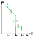
- Selectivity category B comprises circuit breakers providing selectivity by having a short-time withstand current rating and an associated short-time delay. For this category of circuit breaker, manufacturer shall provide the value of short-circuit current (Icw) that can be withstood for a specified time.
It is possible to delay the tripping of this type circuit breaker, where the fault-current level is lower than this short-time withstand current rating (Icw) (see Figure 4).
This is generally applied to power open type or “Air” circuit breakers and to certain heavy-duty molded-case types. Icw is the maximum current that the B category circuit breaker can withstand, thermally and electrodynamically, without sustaining damage, for a period of time given by the manufacturer.
- Selectivity category A comprises all other circuit breakers. This category of circuit breaker has no deliberate delay in the operation of the “instantaneous” short-circuit magnetic tripping device (see Figure 5). Usually molded-case type circuit breakers or modular circuit breaker are category A These circuit breakers may provide selectivity under short-circuit conditions by other means. But manufacturer will not provide Icw value.
Rated making capacity (Icm)
Icm is the highest instantaneous value of current that the circuit-breaker can establish at rated voltage in specified conditions. In AC systems this instantaneous peak value is related to Icu (i.e. to the rated breaking current) by the factor k, which depends on the power factor (cos φ) of the short-circuit current loop (as shown in Template:FigureRef ).
| Icu | cosφ | Icm = kIcu |
|---|---|---|
| 6 kA < Icu ≤ 10 kA | 0.5 | 1.7 x Icu |
| 10 kA < Icu ≤ 20 kA | 0.3 | 2 x Icu |
| 20 kA < Icu ≤ 50 kA | 0.25 | 2.1 x Icu |
| 50 kA ≤ Icu | 0.2 | 2.2 x Icu |
Example: A Masterpact NW08H2 circuit-breaker has a rated breaking capacity Icu of 100 kA. The peak value of its rated making capacity Icm will be 100 x 2.2 = 220 kA.
Rated service short-circuit breaking capacity (Ics)
The rated breaking capacity (Icu) or (Icn) is the maximum fault-current a circuit-breaker can successfully interrupt without being damaged. The probability of such a current occurring is extremely low, and in normal circumstances the fault-currents are considerably less than the rated breaking capacity (Icu) of the CB. On the other hand it is important that high currents (of low probability) be interrupted under good conditions, so that the CB is immediately available for reclosure, after the faulty circuit has been repaired. It is for these reasons that a new characteristic (Ics) has been created, expressed as a percentage of Icu, viz: 25, 50, 75, 100% for industrial circuit-breakers. The standard test sequence is as follows:
- O - CO - COTemplate:Fn (at Ics)
- Tests carried out following this sequence are intended to verify that the CB is in a good state and available for normal service
For domestic CBs, Ics = k Icn. The factor k values are given in IEC 60898 table XIV.
In Europe it is the industrial practice to use a k factor of 100% so that Ics = Icu.
Fault-current limitation
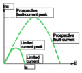
The fault-current limitation capacity of a CB concerns its ability, more or less effective, in preventing the passage of the maximum prospective fault-current, permitting only a limited amount of current to flow, as shown in Figure 6.
The current-limitation performance is given by the CB manufacturer in the form of curves (see Template:FigRef).
- Diagram (a) shows the limited peak value of current plotted against the rms value of the AC component of the prospective fault current (“prospective” fault-current refers to the fault-current which would flow if the CB had no current-limiting capability)
- Limitation of the current greatly reduces the thermal stresses (proportional I2t) and this is shown by the curve of diagram (b) of Template:FigureRef, again, versus the rms value of the AC component of the prospective fault current.
LV circuit-breakers for domestic and similar installations are classified in certain standards (notably European Standard EN 60 898). CBs belonging to one class (of current limiters) have standardized limiting I2t let-through characteristics defined by that class.
In these cases, manufacturers do not normally provide characteristic performance curves.
The advantages of current limitation
The use of current-limiting CBs affords numerous advantages:
- Better conservation of installation networks: current-limiting CBs strongly attenuate all harmful effects associated with short-circuit currents
- Reduction of thermal effects: Conductors (and therefore insulation) heating is significantly reduced, so that the life of cables is correspondingly increased
- Reduction of mechanical effects: forces due to electromagnetic repulsion are lower, with less risk of deformation and possible rupture, excessive burning of contacts, etc.
- Reduction of electromagnetic-interference effects:
- Less influence on measuring instruments and associated circuits, telecommunication systems, etc.
These circuit-breakers therefore contribute towards an improved exploitation of:
- Cables and wiring
- Prefabricated cable-trunking systems
- Switchgear, thereby reducing the ageing of the installation
Example
On a system having a prospective shortcircuit current of 150 kA rms, a Compact L circuit-breaker limits the peak current to less than 10% of the calculated prospective peak value, and the thermal effects to less than 1% of those calculated.
Cascading of the several levels of distribution in an installation, downstream of a limiting CB, will also result in important savings.
The technique of cascading allows, in fact, substantial savings on switchgear (lower performance permissible downstream of the limiting CB(s)) enclosures, and design studies, of up to 20% (overall).
Selective protection schemes and cascading are compatible, in the Compact NSX range, up to the full short-circuit breaking capacity of the switchgear.


